Flexible stent with excellent expandability and trackability

a flexible stent and expandable technology, applied in the field of flexible stents with can solve the problems of difficult to reduce the gap between the two waved elements to less than 40 m, and the radial strength of the stent, and achieve excellent expandability and trackability and good radial strength

Inactive Publication Date: 2007-01-11
NIPRO CORP
View PDF6 Cites 57 Cited by
  • Summary
  • Abstract
  • Description
  • Claims
  • Application Information

AI Technical Summary

Benefits of technology

[0010] In view of the above circumstances, the present invention has been made to provide a flexible stent with excellent expandability and trackability,

Problems solved by technology

Firstly, it is difficult to reduce the gap between the two waved elements to less than 40 μm because of present technical problems.
Secondary, t

Method used


Image

  • Flexible stent with excellent expandability and trackability
  • Flexible stent with excellent expandability and trackability
  • Flexible stent with excellent expandability and trackability

Examples


embodiment 1

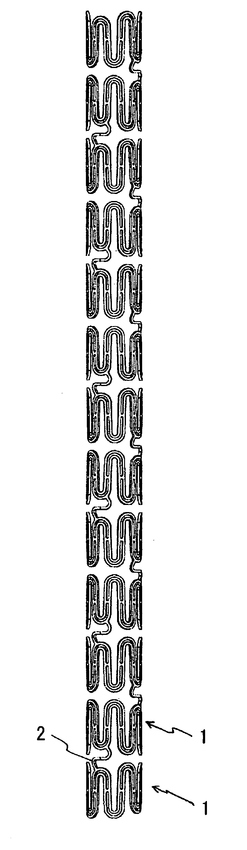
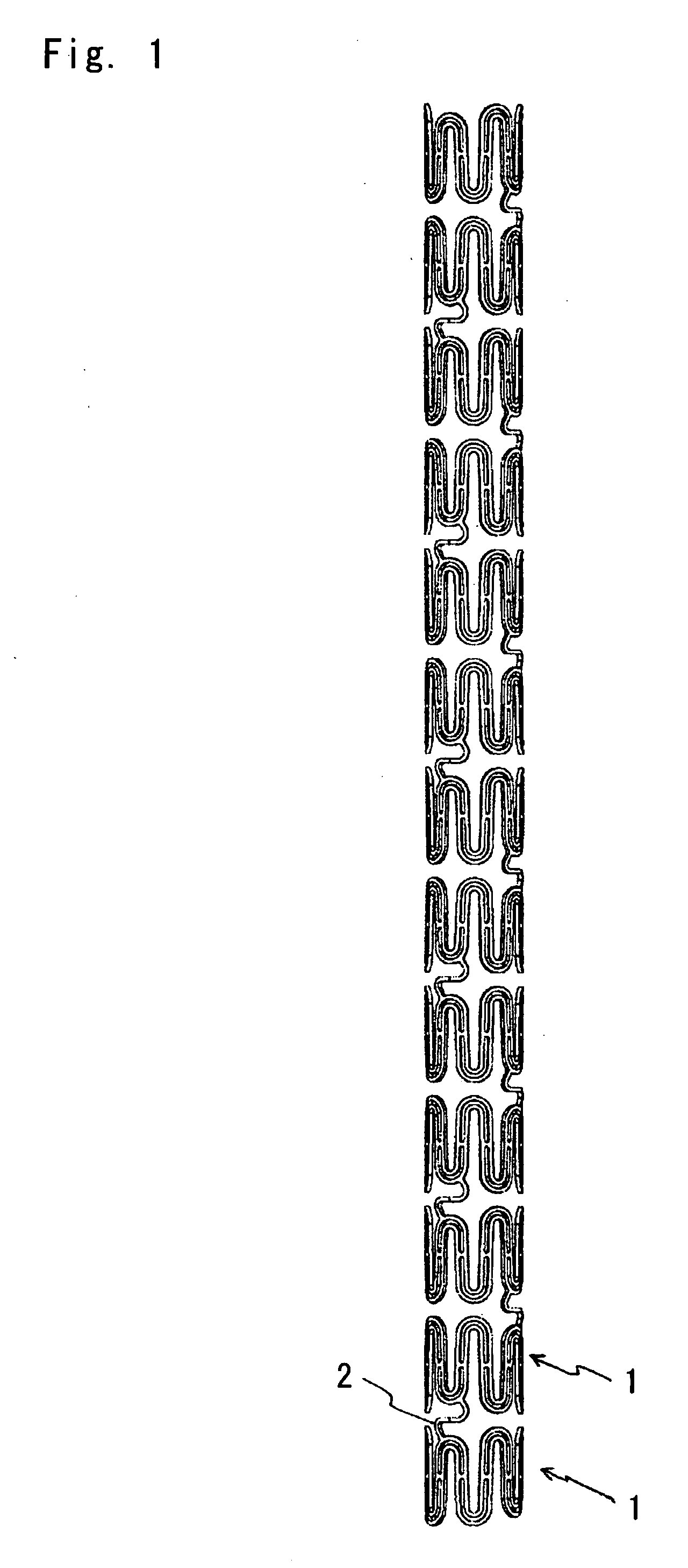
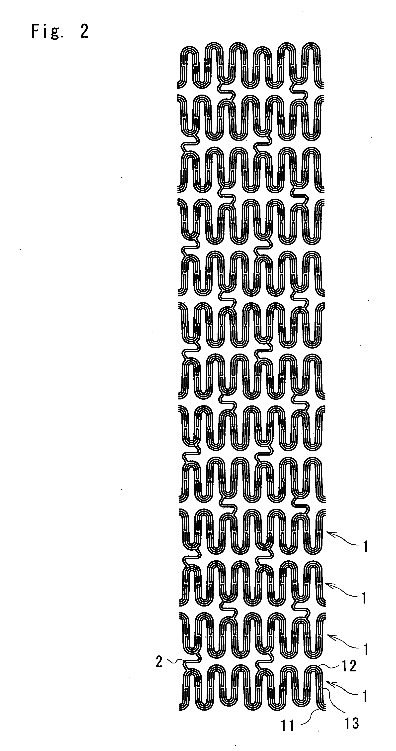
[0036] Firstly, a first embodiment of the present invention will be explained below with reference to FIGS. 1-4. FIG. 1 is a plan view of a stent according to one embodiment of the present invention; FIG. 2 is a development of the stent shown in FIG. 1; FIG. 3 is a plan view illustrating an expanded state of the stent shown in FIG. 1; and FIG. 4 is a partially enlarged view of FIG. 2.

[0037] As shown in FIGS. 1-3, a stent of the first embodiment is a radially expandable tubular member comprising thirteen annular members 1 arranged in an axial direction thereof to keep cavities of the living body open, and connecting members 2 arranged between adjoining annular members 1 to connect them with two connecting members 2. As shown in detail in FIG. 4, each annular member 1 in an developed state is composed of two waved elements 11, 12 which repeatedly meander in parallel with each other like a wave train and which are coupled by coupling elements 13 at an intermediate position between bot...

embodiment 2

[0044] Embodiment 2 of the present invention will be demonstrated below with reference to FIG. 5.

[0045] The stent of embodiment 2 has the same configuration as that of the stent of embodiment 1 except for that the gap between the wave crests and the gap between the wave troughs are uneven and are narrowed at the top or bottom portions of the wave crests or wave troughs. As shown in FIG. 5, the gap 14A between the crest portion (111) of the first waved element 11 and the crest portion (121) of the second waved element 12 and the gap 14B between the trough portion (112) of the first waved element 11 and the trough portion (122) of the second waved element 12 are uneven and the gaps 14A and 14B are gradually narrowed from the intermediate portion of the annular member 1 to the top 121 or bottom 112 of the wave crests or wave trough. The gap 14A, 14B at the top 121 or bottom 112 of the wave crests or wave trough is set to 40 μm, which is smaller than the gap (60 μm) in other parts by 2...

embodiment 3

[0047] Embodiment 3 of the present invention will be demonstrated below with reference to FIG. 6.

[0048] The stent of embodiment 3 has the same configuration as that of the stent of embodiment 1 except for that the gap between the wave crest and the gap between the wave troughs are uneven and are widened at the top or bottom regions of the wave crests or wave troughs as compared with other regions of the wave crests or wave troughs.

[0049] As shown in FIG. 6, the gap 14A between the crest portion (111) of the first waved element 11 and the crest portion (121) of the second waved element 12 and the gap 14B between the trough portion (112) of the first waved element 11 and the trough portion (122) of the second waved element 12 are uneven and the gaps 14A and 14B are gradually widened from the intermediate portion of the annular member 1 to the top 121 or bottom 112 of the wave crest or wave trough. The gap 14A, 14B at the top 121 or bottom 112 of the wave crests or wave trough is 80 ...


PUM


Abstract

A flexible stent with excellent trackability and expandability comprises a plurality of radially expandable annular members 1 arranged in an axial direction thereof, and connecting elements 2 for connecting adjoining two annular members 1, adjoining annular members 1, 1 being connected by one or more of the connecting elements 2. The annular members 1 are radially expandable and each annular member 1 comprises two waved elements 11, 12 that repeatedly meander in parallel with or substantially parallel with each other and are coupled by coupling elements 13 at intermediate portions between wave crests and wave troughs of the waved elements 11, 12. The stent is excellent in trackability, which in turn makes it possible to pass through three-dimensionally meandering lumens. The stent is excellent in radial strength, substantially free from shortening and easy to provide a lateral hole.

Description

[0001] The present invention relates to a stent to be implanted in a living body to maintain a luminal diameter of a body cavity such as the blood vessel. BACKGROUND OF THE INVENTION [0002] Stents have been used to expand luminal diameters of body cavities such as blood vessels and keep the resultant luminal sizes of the body cavities. There are various methods for expanding such a stent, including balloon dilation, self-expansion using a shape memory material, mechanical expansion or the like. Among them, the most widely used method is the balloon dilation. In the balloon dilation, a stent is introduced into a desired site in the body together with a balloon catheter and expanded by inflation of the balloon to dilate a luminal diameter of the body cavity. The stent generally comprises luminal diameter-holding portions for dilating and holding the luminal diameter of the body cavity such as the blood vessel, and joint portions for connecting the luminal diameter-holding portions in ...

Claims


Application Information

Patent Timeline
IPC IPC(8): A61F2/06A61F2/915A61M29/00A61M29/02
CPCA61F2/91A61F2/915A61F2002/91508A61F2002/91516A61F2230/0013A61F2002/91541A61F2002/91558A61F2002/91575A61F2002/91525
Inventor SANO, YOSHIHIKO
Owner NIPRO CORP
Why Eureka
Try Eureka