Electronic component mounting apparatus

a technology for mounting apparatuses and components, applied in metal working apparatuses, printed circuit manufacture, manufacturing tools, etc., can solve problems such as reducing the pickup rate and error in picking components

Inactive Publication Date: 2007-01-18
HITACHI HIGH TECH INSTR CO LTD
View PDF10 Cites 33 Cited by
  • Summary
  • Abstract
  • Description
  • Claims
  • Application Information

AI Technical Summary

Benefits of technology

[0007] The invention provides an electronic component mounting apparatus that includes a feeder base, and a component feeding unit disposed on the feeder base and feeding electronic components stored in a storage tape so that each of the electronic components is advanced to a component pickup position where a suction nozzle is configured to pick up the electronic component fed by the component feeding unit for mounting the electronic component on a printed board. The apparatus also includes a seam detection device provided for the component feeding unit and detecting a connection tape connecting two storage tapes, a counter counting the feeding of the electronic components to the component pickup position after the seam detection device detects the connection tape, a recognition camera taking an image of one of storage concave portions of the storage tape storing the electronic components therein when the counting of the feeding reaches a predetermined number, a recognition processing device performing a recognition processing to the image taken by the recognition camera, and a control device adjusting the component pickup position based on a result of the recognition processing of the recognition processing device.
[0008] The invention also provides an electronic component mounting apparatus that includes a feeder base, and a component feeding unit disposed on the feeder base and feeding electronic components stored in a storage tape so that each of the electronic components is advanced to a component pickup position where a suction nozzle is configured to pick up the electronic component fed by the component feeding unit for mounting the electronic component on a printed board. The apparatus also includes a detection device provided for the component feedin

Problems solved by technology

However, in a case where the component feeding unit is dismounted from the feeder base, the storage tapes are connected to each other with a connection tape, and then the component feeding unit is mounted back on the feeder base when a shortage of electronic components occurs,

Method used


Image

  • Electronic component mounting apparatus
  • Electronic component mounting apparatus
  • Electronic component mounting apparatus

Examples


Embodiment Construction

[0021] An electronic component mounting apparatus having an electronic component feeding device and an electronic component mounting apparatus body will be described with reference to the attached drawings. This electronic component mounting apparatus is a so-called multifunctional chip mounter, which can mount a variety of electronic components on a printed board P.

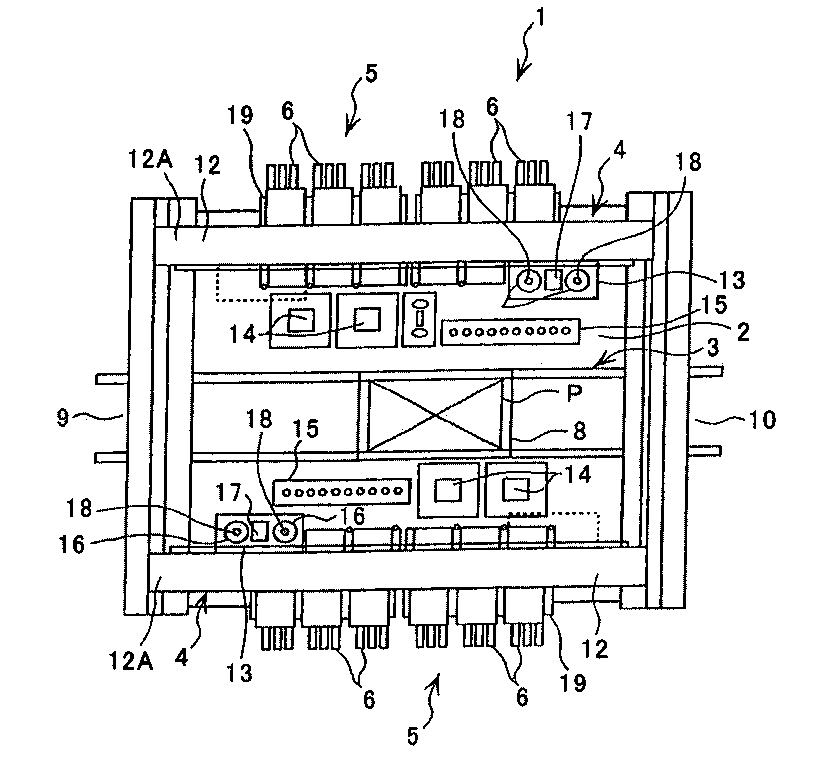
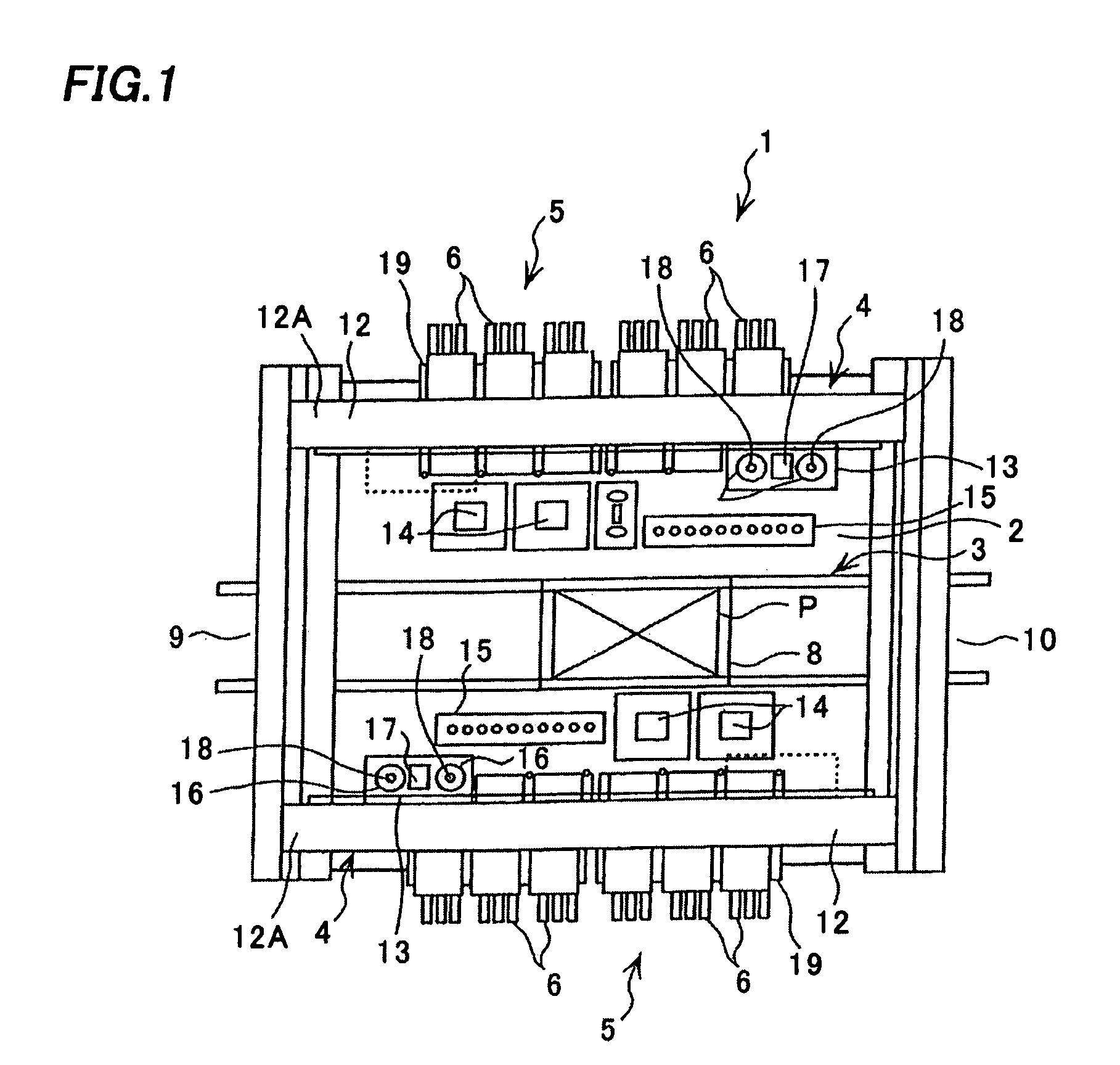
[0022]FIG. 1 is a plan view of the electronic component mounting apparatus. An electronic component mounting apparatus body 1 includes a base 2, a conveyer portion 3 extending in a lateral direction in a center of the base 2, and two component mounting portions 4 and two component feeding portions 5 each provided on the front (on a lower side of FIG. 1) and the rear (on an upper side of FIG. 1) of the base 2. Each of the component feeding portions 5 is detachably set with a plurality of component feeding units 6 as the electronic component feeding device, thereby forming the electronic component mounting apparatus.

[002...


PUM


Abstract

This invention is directed to prevention of reduction of a pickup rate of an electronic component when a component feeding unit is dismounted from a feeder base and mounted back thereon. A CPU sends a feeding command to a component feeding unit feeding an electronic component belonging to a first step number, and drives a servomotor and a drive motor of the feeding unit to perform a component feeding operation and so on. After then, when the CPU judges that the feeding unit is dismounted from the feeder base and mounted back thereon, the CPU drives a X axis drive motor and a Y axis drive motor to move a board recognition camera to the pickup position of the feeding unit, the camera takes an image of a storage portion of a storage tape, and a recognition processing device performs recognition processing to the image. A correction value based on this recognition result is stored in a RAM, the X axis drive motor and the Y axis drive motor are driven taking this correction value into account, a vertical axis drive motor is driven, and a suction nozzle lowers and picks up the electronic component.

Description

CROSS-REFERENCE OF THE INVENTION [0001] This application is based on Japanese Patent Applications No. No. 2005-192116, the content of which is incorporated herein by reference in its entirety. BACKGROUND OF THE INVENTION [0002] 1. Field of the Invention [0003] The invention relates to an electronic component mounting apparatus having a plurality of component feeding units aligned on a feeder base, the component feeding unit feeding an electronic component stored in a storage tape to a component pickup position, in which a suction nozzle picks the electronic component fed by the component feeding unit and mounts the electronic component on a printed board. [0004] 2. Description of the Related Art [0005] In this kind of electronic component mounting apparatus, particularly in a high-speed gantry-type mounting device, since the component feeding units are fixed and not moved, there are rapidly increasing users employing the so-called splicing where storage tapes are connected to each o...

Claims


Application Information

Patent Timeline
IPC IPC(8): B23P19/00
CPCH05K13/021H05K13/0417H05K13/08Y10T29/4913Y10T29/49133Y10T29/53178Y10T29/53174Y10T29/49131Y10T29/49146H05K13/0419H05K13/081H05K13/0215H05K13/02
Inventor WATANABE, AKIOKAWAI, AKIHIROONO, TETSUJIKAMEDA, MAKIOOYAMA, KAZUYOSHI
Owner HITACHI HIGH TECH INSTR CO LTD
Why Eureka
Try Eureka