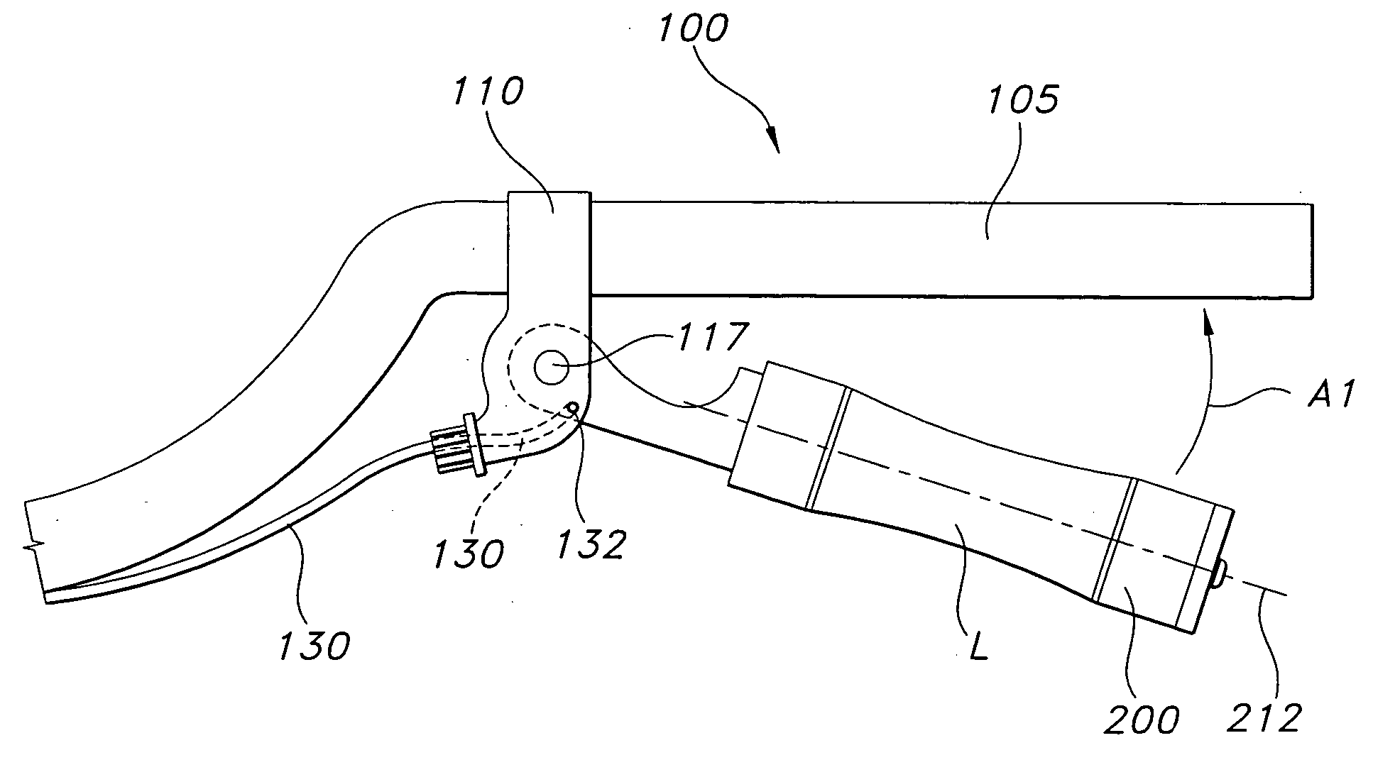
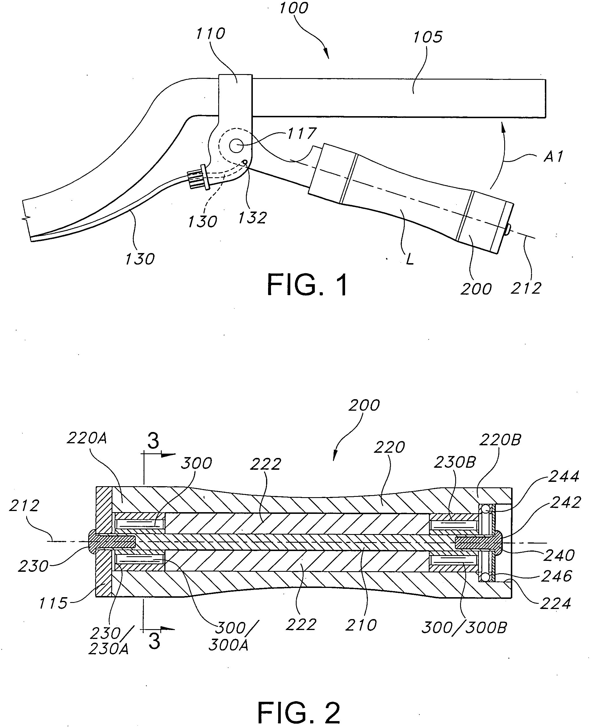
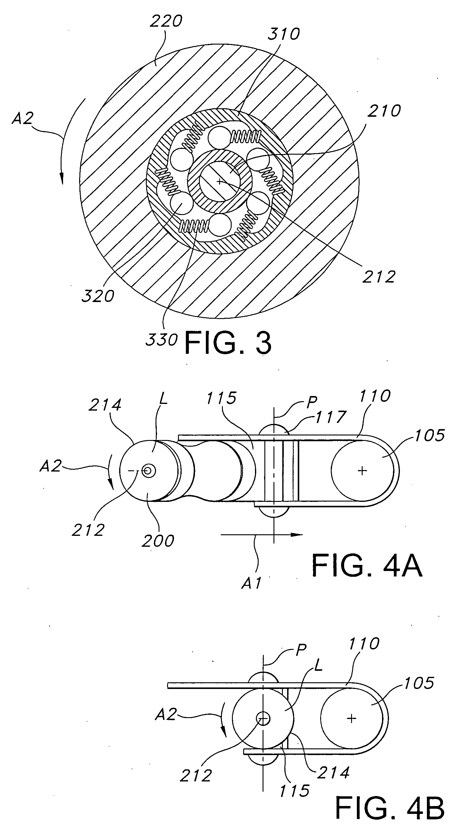
[0009] The present invention is an actuator assembly that rotates about a central axis that extends through the lever as it is being pulled to actuate a mechanism. The rotating action of the lever allows it to travel from the fingertips toward the base of the fingers of the operator, where the operator has much greater strength and control. The actuator assembly according to the invention comprises a shaft, a rotation-restriction mechanism mounted on the shaft, a sleeve assembled over the rotation-restriction mechanism and the shaft, and an attachment means. The rotation-restriction mechanism allows the sleeve to rotate in one direction, but not in the other. The
advantage of this actuator assembly is that, as the operator pulls the lever, i.e. the shaft, to an actuation position, the sleeve rotates in a direction that facilitates rolling travel of the sleeve from the fingertips in toward the base of the fingers near the palm of the hand. When fully actuated, the lever of the actuator assembly according to the invention is positioned somewhere between the
knuckle joint and the
second finger joint. In this position, the operator is able to exercise maximum
hand strength and exert the greatest amount of control over the lever.
[0011] Typical applications of the actuator assembly according to the invention are for brake and clutch levers on bicycles and motorcylces, referred to hereinafter collectively as “bikes.” In such applications, the lever is biased toward a resting or open position. The operator supports the palm of the hand on the handlebar, grasps the lever with the fingertips and pulls the lever toward the handlebar. As the lever is pulled toward the handlebar, the force exerted on the sleeve causes it to rotate about the shaft axis. This allows the sleeve to rollingly travel along the gripping surface of the fingertips in toward the
knuckle joint or the palm of the hand. With conventional bike levers, there is no rolling action, and the fingertips themselves do not shift position relative to the lever, but move with the lever toward the palm. When the force exerted on the lever is relaxed, the lever moves back toward the resting position, but the lever does not roll during this part of the travel. The lever exerts the greatest amount of biasing force toward the resting position when it is completely pulled in and, thus, at the beginning of its outward travel. This force diminishes as the lever approaches the resting position. Advantageously, as the lever is released from its actuated position, the lever is positioned at the base of the fingers, between the kunckle joint and the
second finger joint, where the operator has the greatest strength and control. As the lever travels toward the resting position, it slides along the gripping surface of the fingers toward the fingertips. Less force is required to control the lever as it moves toward the resting position and toward the tips of the fingers. Thus, the actuator assembly according to the invention, increases the ease and operator control over the motion of the lever and, consequently, reduces fatigue and improves improves
operational safety.
[0012] Other applications for the actuator assembly according to the invention include
grippers for scisssor-action tools, such as plier, shears, and cutters, and hand exercise devices. Typical for the scissor-action tools is a pivot point connecting two elongate members, one end of a member being a gripper, the other end being the tool end. The two members are connected in an X configuration at the pivot point. The tool is operated by squeezing the
grippers together, or moving one gripper toward the other. Often, the grippers are far apart, are biased to an open position, and / or require significant amount of strength to operate. Persons with small hands have a particularly hard time operating such tools, and often suffer fatigue in the hands. The actuator assembly according to the invention is to be incorporated into one of the grippers, which is referred to hereinafter as an “active” gripper, the other gripper being a “passive” gripper. The passive gripper lies in the palm of the operator's hand and the active grippper is grasped by the fingertips. During the process of pulling the active gripper toward the passive gripper, the active gripper, having a sleeve, a one-way bearing bearing, and a shaft, rolls along the gripping surfaces of the fingers toward the base of the fingers near the palm of the hand. As described above, this allows the operator to exercise greater control over the tool, with less fatigue, because the greatest force required to operate the tool is applied while the active gripper is moving toward or is at the base of the fingers. Analogously, the actuator assembly may be incorporated into one of the grippers of hand exercise devices that comprise a coiled spring with two grippers.
[0013] The actuator assembly according to the invention may be incorporated into countless other devices that require that the operator exert force and control over the motion or position of a lever. Another example of a useful application of the actuator assembly is with a trigger of a gun. The conventional trigger is squeezed toward a trigger point. Ideally, the motion exerted on the trigger is smooth and continuous, and sometimes, very slow. This smooth, continuous, slow squeezing motion is difficult to accomplish without repetitive training. The actuator assembly may be incorporated into the trigger assembly, to allow the trigger lever to roll along the inside of the operator's
trigger finger as the trigger is squeezed, which makes it easier for the operator to control the squeezing motion of the
trigger finger.

