

Coil failure detection system for general-purpose engine
- Summary
- Abstract
- Description
- Claims
- Application Information
AI Technical Summary
Problems solved by technology
Method used
Image

Examples
Embodiment Construction
[0013] A coil failure detection system for a general-purpose engine according to an embodiment of the present invention will now be explained with reference to the attached drawings.
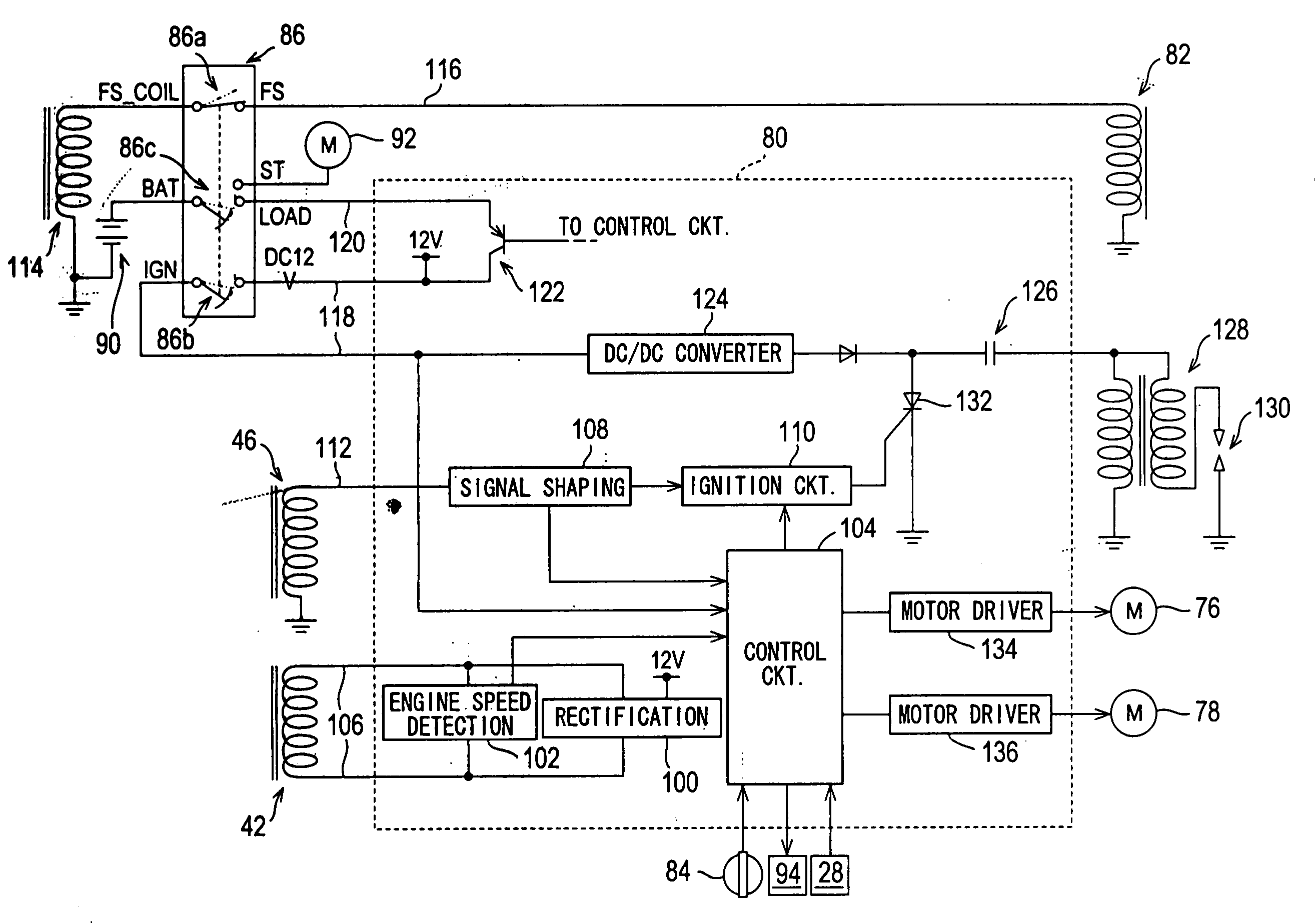
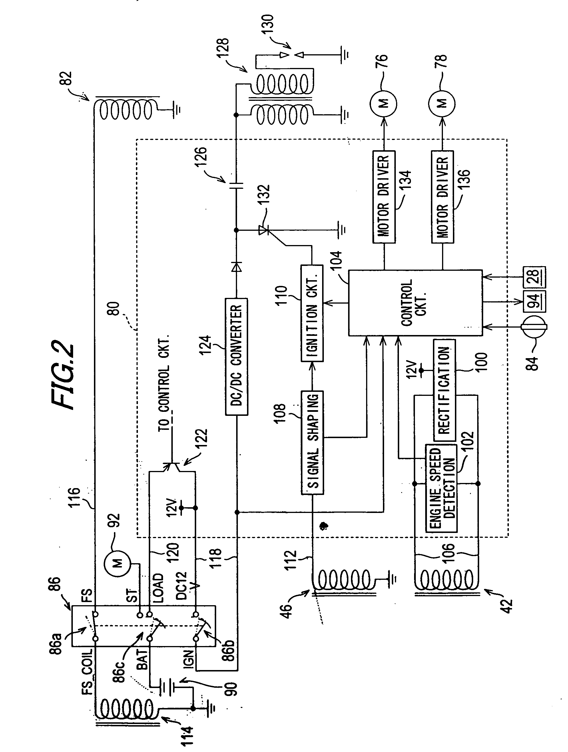
[0014]FIG. 1 is a diagram of the coil failure detection system for a general-purpose engine according to the preferred embodiment.
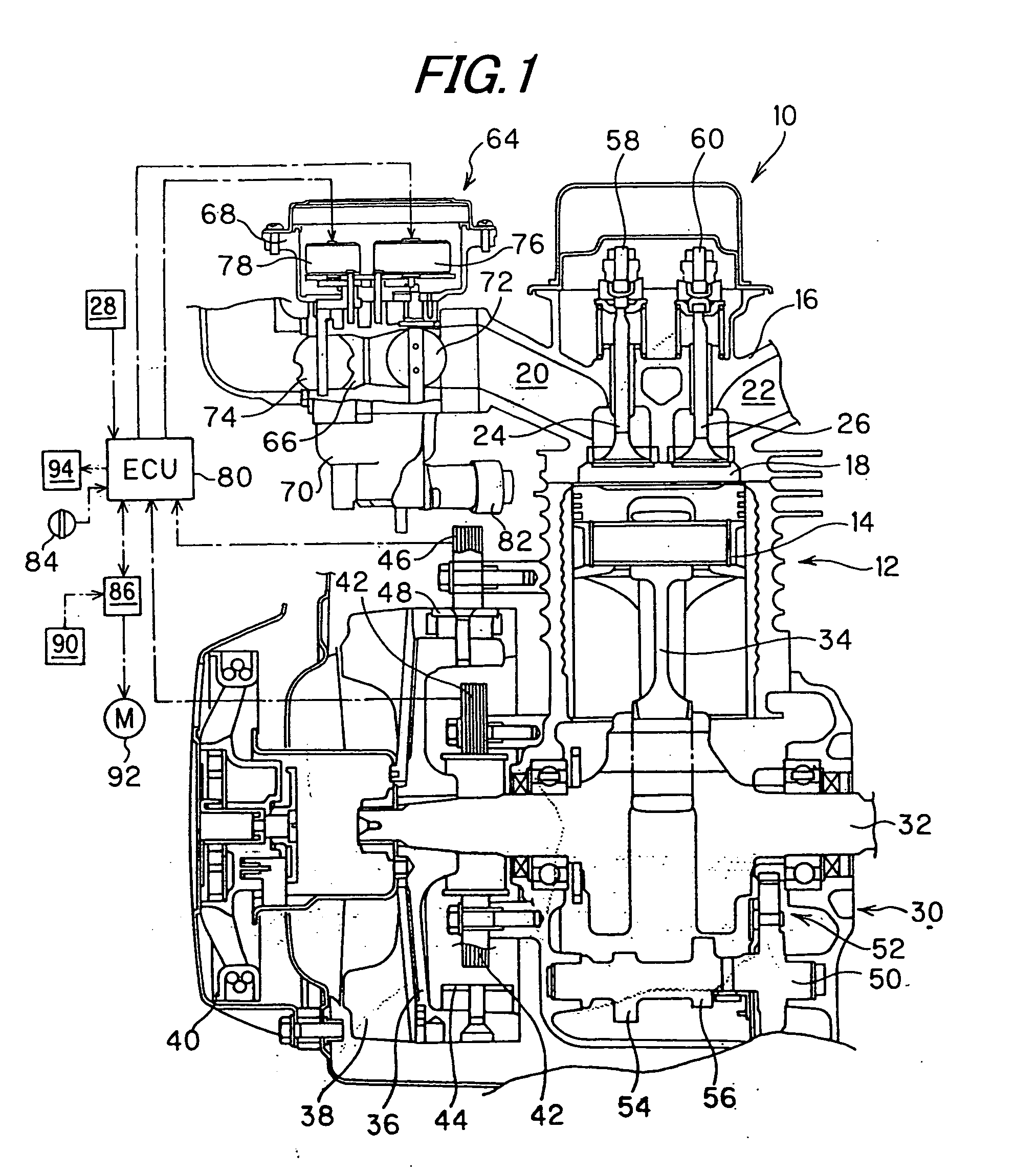
[0015] Reference numeral 10 in FIG. 1 designates a general-purpose or industrial engine. The engine 10 is an air-cooled, four-cycle, single-cylinder OHV model with a displacement of, for example, 400 cc. The engine 10 is suitable for use as the prime mover of a generator, agricultural machine or any of various other kinds of equipment.
[0016] The engine 10 has a cylinder (cylinder block) 12 accommodating a piston 14 that can reciprocate therein. A cylinder head 16 is attached to the top of the cylinder 12. A combustion chamber 18 is formed in the cylinder head 16 so as to face the crown of the piston 14. An intake port 20 and an exhaust port 22 are provided in communication ...
PUM
 Abstract
Description
Claims
Application Information