Container treatment device with a gas curtain

a treatment device and container technology, applied in the direction of packaging goods, liquid bottling, packaging under special atmospheric conditions, etc., can solve the problems of air expulsion from the container, drawback, direction of the gas curtain from the treatment implement to the container, etc., to make the clean room housing superfluous, the equipment design becomes very simpl

Inactive Publication Date: 2007-01-18
POPPLAU JENS H
View PDF5 Cites 7 Cited by
  • Summary
  • Abstract
  • Description
  • Claims
  • Application Information

AI Technical Summary

Benefits of technology

[0006] The container mouth may be configured in the flow component issuing downward from the slot nozzles. If the plane of symmetry is configured below the container mouth, a clean gas curtain is implemented that runs past the mouth above the plane and that protects the entire treatment site against contamination. The other portion of the rammed flow runs downward past the container and precludes the upward portion of the rammed flow from aspiring contaminated gas from below from the region between the nozzles and the container. The clean gas flow directed past the container mouth to the treatment implement therefore is protected in an extraordinarily effective manner against contaminant penetration and is directed in the vicinity of the container mouth away from this mouth in a manner that no gas is forced into the container or toward the mouth, a gas transport instead being generated by means of the upward-pointing gas curtain and entraining contaminants present at the container and in particular also entraining air issuing from the container during the filling procedure. Because the exiting air and the gas curtain point in the same direction, interfering turbulences that might move contaminants in undesired directions are precluded.
[0007] According to an embodiment of the invention, the slot nozzles are configured in the free atmosphere, whereby, as already mentioned above, equipment design becomes very simple and makes a clean room housing superfluous.

Problems solved by technology

It is known to treat the container in a clean room that contains the entire equipment even though this measure entails costly enclosure construction.
However, this design also incurs the drawback that the flow direction of the gas curtain is directed from the treatment implement to the container, namely toward the container mouth.
Contaminants piercing the gas curtain may thereby be forced toward the mouth and cause contamination.
When a container is filled in the open, another problem arises, namely that the air expelled from the container, that most of the time is charged with germs and oxygen, will collide in opposite direction to the flowing gas curtain and be strongly perturbed by it.

Method used


Image

  • Container treatment device with a gas curtain
  • Container treatment device with a gas curtain
  • Container treatment device with a gas curtain

Examples


Embodiment Construction

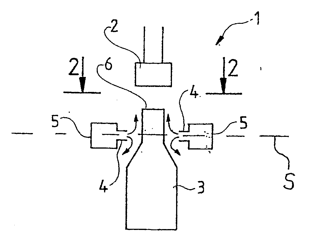
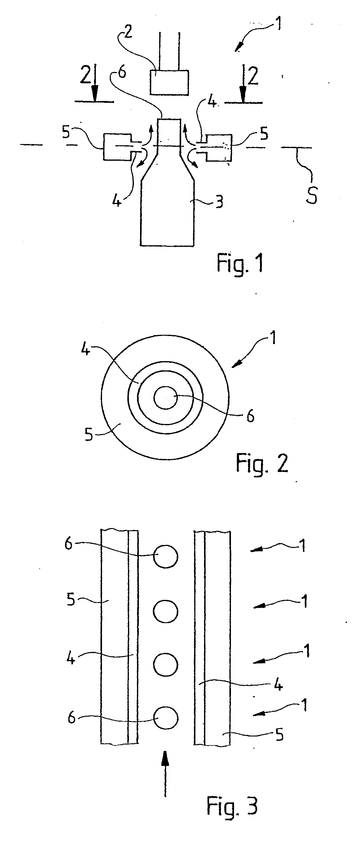
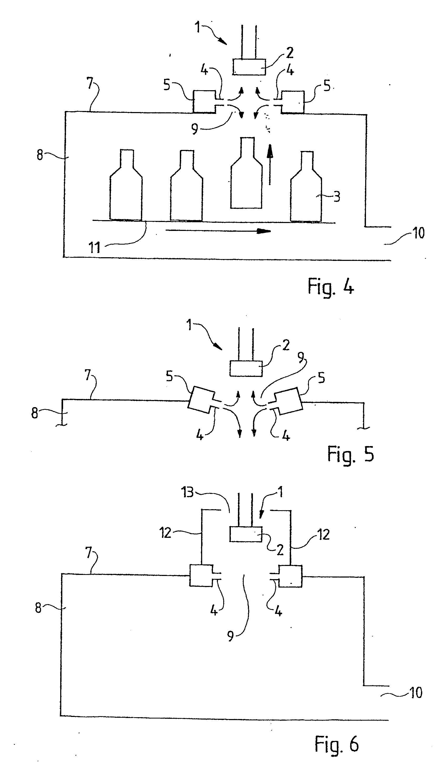
[0023] In much schematized manner, FIG. 1 shows a treatment site 1 fitted with a treatment implement 2 and with a bottle 3 configured in the treatment position underneath the implement. Slot nozzles 4 are mounted at the height of the bottle 3, for instance as shown at the height of its neck, that is, the upper end zone of the bottle 3. The slot directions run perpendicularly to the plane of the drawing, each being fed by a gas pipe 5 which is connected (in a manner not shown) to a compressed clean gas supply. This clean gas foremost must be germ-free. Conventionally, sterilized air is used for such purposes. When oxygen-susceptible beverages such as beer are to be filled into the bottles, then a clean gas free of oxygen, for instance CO2 or N2, must be used.

[0024] As shown by FIG. 1, the slot nozzles point at each other in such a way that they issue the gas in a flow direction indicated by the arrows one against the other, the rammed flow generating up and down flow components in t...


PUM

PropertyMeasurementUnit
of symmetryaaaaaaaaaa
symmetryaaaaaaaaaa
impedanceaaaaaaaaaa

Abstract

Equipment for treating open beverage containers (3), e.g. by filling or closing, comprising: a treatment site (1), to which a container (3) can be delivered for treatment, and at which a treatment element (2) is situated that acts upon the mouth (6) of the container (3) from above, and slit nozzles (4), which are situated to the side of the treatment site (1), and discharge clean gas, and which are designed for producing a gas curtain that protects the area of the mouth (6) of the container (3). The invention is characterized in that the slit nozzles (4) are placed in, in essence, oppositely oriented jet directions whereby between the slit nozzles (4), a pressure flow is produced having flow components exiting upward and downward from the area of the slit nozzles (4) perpendicular to the plane of symmetry (S).

Description

BACKGROUND OF THE INVENTION [0001] Open beverage containers such as cans or bottles must be treated under conditions that are as clean as possible, in order to preclude contaminating the containers with germs that would degrade the beverage's shelf life and taste. Regarding oxygen-sensitive beverages such as beer, exposure to oxygen also must be precluded during treatment, for instance during filling. It is known to treat the container in a clean room that contains the entire equipment even though this measure entails costly enclosure construction. [0002] The German patent document DE 101 14 660 C2 discloses equipment of this kind where merely the region of the treatment site is protected by a curtain of clean gas against exposure to germs and oxygen. As regards this known design, a slot nozzle is configured at the treatment implement to annularly enclose the implement and projects a tubular gas curtain downward and in the direction of the container axis. [0003] This design eliminat...

Claims


Application Information

Patent Timeline
Patent Type & Authority Applications(United States)
IPC IPC(8): B65B1/04B65B31/02B67C3/22B67C3/26
CPCB65B31/025B67C2003/2697B67C2003/2691B67C3/22
Inventor POPPLAU, JENS H.
Owner POPPLAU JENS H
Why Eureka
Try Eureka