Two-point modulation type phase modulation apparatus, polar modulation transmission apparatus, wireless transmission apparatus and wireless communication apparatus

a phase modulation and polar modulation technology, applied in the direction of phase-modulated carrier systems, pulse automatic control, electrical apparatus, etc., can solve the problem of increasing the number of dependent circuits consisting of resistors and capacitors, affecting the performance of anti-alias filter b>7/b>, and provoking deterioration in noise characteristics, etc., to achieve the effect of superior modulation precision and low cos

Active Publication Date: 2007-01-18
PANASONIC CORP
View PDF6 Cites 25 Cited by
  • Summary
  • Abstract
  • Description
  • Claims
  • Application Information

AI Technical Summary

Benefits of technology

[0018] It is therefore an object of the present invention to provide two-point modulation phase modulation apparatus capable of obtaining an RF phase modulation signal with superior modulation precision that does not require an increase in sampling frequency (i.e. lowpower consumption) even for wide frequency band modulation and that employs an anti-alias filter of a simple configuration (i.e. low cost).

Problems solved by technology

However, when PLL frequency bandwidth is made wide, this invites deterioration in noise characteristics.
However, increasing the order of anti-alias filter 7 means increasing the number of dependent circuits consisting of resistors and capacitors, and the configuration of the anti-alias filter 7 therefore becomes complex.
However, it is necessary to increase the clock frequency in order to increasing the sampling frequency fs of D / A converter 6 which raises another problem of the power consumption increasing as a result.

Method used


Image

  • Two-point modulation type phase modulation apparatus, polar modulation transmission apparatus, wireless transmission apparatus and wireless communication apparatus
  • Two-point modulation type phase modulation apparatus, polar modulation transmission apparatus, wireless transmission apparatus and wireless communication apparatus
  • Two-point modulation type phase modulation apparatus, polar modulation transmission apparatus, wireless transmission apparatus and wireless communication apparatus

Examples


embodiment 1

(Embodiment 1)

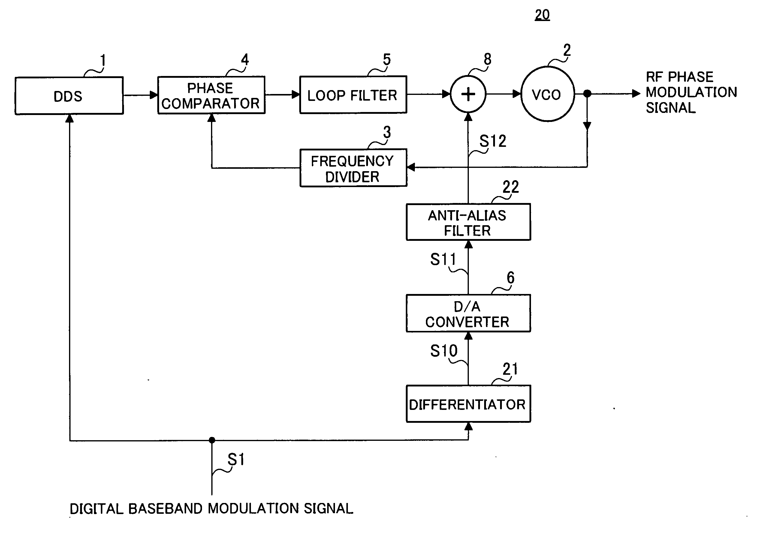
[0038] A configuration for two-point modulation phase modulation apparatus according to Embodiment 1 of the present invention is shown in FIG. 5. Two-point modulation phase modulation apparatus 20 has PLL circuit made up of a voltage controlled oscillator (VCO) 2 with an oscillation frequency changing according to a voltage of a control voltage terminal, frequency divider 3 that frequency-divides an RF phase modulation signal outputted by VCO2, phase comparator 4 that compares an output signal of frequency divider 3 and phase of a reference signal and outputs a signal according to the phase difference, and loop filter 5 that averages and outputs an output signal of phase comparator 4.

[0039] Further, two-point modulation phase modulation apparatus 20 has DDS (Direct Digital Synthesizer) 1. DDS1 forms a reference signal based on input digital baseband modulation signal S1 and transmits this to phase comparator 4. Phase comparator 4 compares the phases of the reference s...

embodiment 2

(Embodiment 2)

[0049] A configuration for a two-point modulation phase modulation apparatus 30 of this embodiment is shown in FIG. 7, with portions corresponding to FIG. 5 being given the same reference numerals. Two-point modulation phase modulation apparatus 30 of this embodiment differs from the two-point modulation phase modulation apparatus 20 of Embodiment 1 in that an integrator 31 is used in place of the anti-alias filter 22. It is therefore possible to obtain the same results as for Embodiment 1.

[0050] Here, the frequency characteristics of integrator 31 are set to be a narrower frequency band than the PLL modulation frequency bandwidth. The frequency characteristics (gradient) of differentiator 21 are set to be the opposite characteristics to the attenuation characteristics (gradient) of integrator 31.

[0051] The operation of two-point modulation phase modulation apparatus 30 of this embodiment is shown in FIG. 8. Integrator 31 shown in FIG. 8B has the same frequency chara...

embodiment 3

(Embodiment 3)

[0053] A configuration for a two-point modulation phase modulation apparatus 40 of this embodiment is shown in FIG. 9, with portions corresponding to FIG. 5 being given the same reference numerals. Two-point modulation phase modulation apparatus 40 of this embodiment differs from the two-point modulation phase modulation apparatus 20 of Embodiment 1 in that a pre-emphasis filter 41 is used in place of differentiator 21.

[0054] The frequency characteristic of the pre-emphasis filter 41 is set to be the opposite characteristic of the frequency characteristic of anti-alias filter 22.

[0055] The operation of two-point modulation phase modulation apparatus 40 of this embodiment is shown in FIG. 10. As shown in FIG. 10A, a pre-emphasis signal S30 with a high-frequency component amplified by a frequency characteristic of pre-emphasis filter 41 is acquired as a result of passing input digital baseband modulation signal S1 through pre-emphasis filter 41. When this pre-emphasis ...


PUM


Abstract

There provides a two-point modulation phase modulation apparatus capable of obtaining an RF phase modulation signal of superior modulation precision with low power consumption and a simple configuration even in the event of inputting a wide band baseband modulation signal. A differentiator (21) of the opposite characteristics to the attenuation characteristics of anti-alias filter (22) is provided at the front stage of a D/A converter (6). As a result, it is possible to sufficiently suppress an alias signal without raising the sampling frequency of the D/A converter (6) (i.e. low power consumption) using an anti-alias filter (22) of a simple configuration (i.e. low cost) with a low order for a narrower bandwidth than a PLL modulation frequency bandwidth, and it is possible to obtain an RF phase modulation signal where the entire frequency band of input digital baseband modulation signal (S1) is reflected in a superior manner.

Description

BACKGROUND OF THE INVENTION [0001] 1. Field of the Invention [0002] The present invention particularly relates to a two-point modulation phase modulation apparatus modulating a carrier frequency signal using an input digital baseband modulation signal by carrying out two-point modulation using a PLL (Phase Locked Loop), and a polar modulation transmission apparatus, a wireless transmission apparatus, and a wireless communication apparatus using this two-point type phase modulation apparatus. [0003] 2. Description of the Related Art [0004] In the related art, phase modulation apparatus employing PLL's where a carrier signal is modulated by a baseband modulation signal so as to form a transmission signal (i.e. a baseband modulation signal is upconverted to a wireless frequency) are widely employed. In this type of phase modulation apparatus, low cost, low power consumption, superior noise characteristics and modulation precision are generally required. In the case of carrying out modu...

Claims


Application Information

Patent Timeline
Patent Type & Authority Applications(United States)
IPC IPC(8): H03L7/00
CPCH03C3/0925H03C3/0933H04L27/20H03C3/095H03C3/0966H03C3/0941
Inventor HIRANO, SHUNSUKEADACHI, HISASHI
Owner PANASONIC CORP
Why Eureka
Try Eureka