Ink level detecting apparatus having optical fiber to detect the ink level in inkjet printer

Inactive Publication Date: 2007-01-18
SAMSUNG ELECTRONICS CO LTD
View PDF3 Cites 4 Cited by
  • Summary
  • Abstract
  • Description
  • Claims
  • Application Information

AI Technical Summary

Benefits of technology

[0011] The present general inventive concept provides an ink level detecting apparatus that can continuously detect in real time the level of ink remaining in an ink tank using an optical fiber.
[0015] The optical fiber is a thin flexible fiber through which the light propagates. The optical fiber includes a core having a relatively high refractive index and a clad having a relatively small refractive index and which surrounds the core. The optical fiber may be any known conventional optical fiber. When the refractive indices of the core and the clad are smaller, the sensitivity to the change of light intensity due to the curvature change of the optical fiber increases.
[0016] The light source may be any of various light sources such as an LED and a laser diode. A light source which emits near infrared (IR) light when signals are transmitted via an optical fiber may be used. However, to increase the sensitivity to the change of the light intensity due to the curvature change of the optical fiber, a light source which emits light of a relatively short wavelength may be also used. In addition, the light source and the optical fiber may be formed in a single body in order to increase the efficiency and uniformity of incident light.
[0017] The pressuring unit has a plurality of protrusions, changes the curvature of the optical fiber according to the weight of the ink tank by concentrating the load of the ink tank to the protrusions, and presses the optical fiber from both sides. The optical fiber is slightly elastic, and thus the degree of the curvature change of the optical fiber depends on the magnitude of the applied weight. A predetermined tension may be applied to the optical fiber to have an appropriate curvature according to the weight of the ink tank. In addition, the optical fiber may be freely changed according to the displacement of the ink tank, and a separate elastic element may support the ink tank, wherein the displacement of the ink tank is approximately proportional to the weight of the ink tank.
[0018] As such, when the curvature of the optical fiber changes according to the weight of the ink tank, light scatters in an area where the curvature changes and light energy is reduced, thereby reducing the intensity of light at the rear end of the optical fiber. Such a change of the light intensity has a predetermined relationship with the curvature change of the optical fiber, and the degree of the curvature change of the optical fiber has a predetermined relationship with the weight of the ink tank. Therefore, the weight change of the ink tank, that is, the ink consumption, can be detected by detecting the change of the light intensity.

Problems solved by technology

First, if ink is ejected until all the ink is exhausted, an ink ejecting head can get damaged.
If the heating element is heated when there is no ink inside the ink cell, the heating element or peripheral elements may get damaged.
Second, when ink is exhausted and a printing job is stopped during the middle of printing, the partially printed paper and ink printed thereon will be discarded.
That is, the conventional devices do not inform a user of the current ink level in an inkjet printer before the ink level reaches the critical level.
Thus, the user cannot predict when the ink will be exhausted or how many more pages can be printed using the conventional devices.

Method used


Image

  • Ink level detecting apparatus having optical fiber to detect the ink level in inkjet printer
  • Ink level detecting apparatus having optical fiber to detect the ink level in inkjet printer
  • Ink level detecting apparatus having optical fiber to detect the ink level in inkjet printer

Examples


Embodiment Construction

[0032] The present invention will now be described more fully with reference to the accompanying drawings, in which exemplary embodiments of the invention are shown. Like reference numerals in the drawings denote like elements, and thus their description will be omitted.

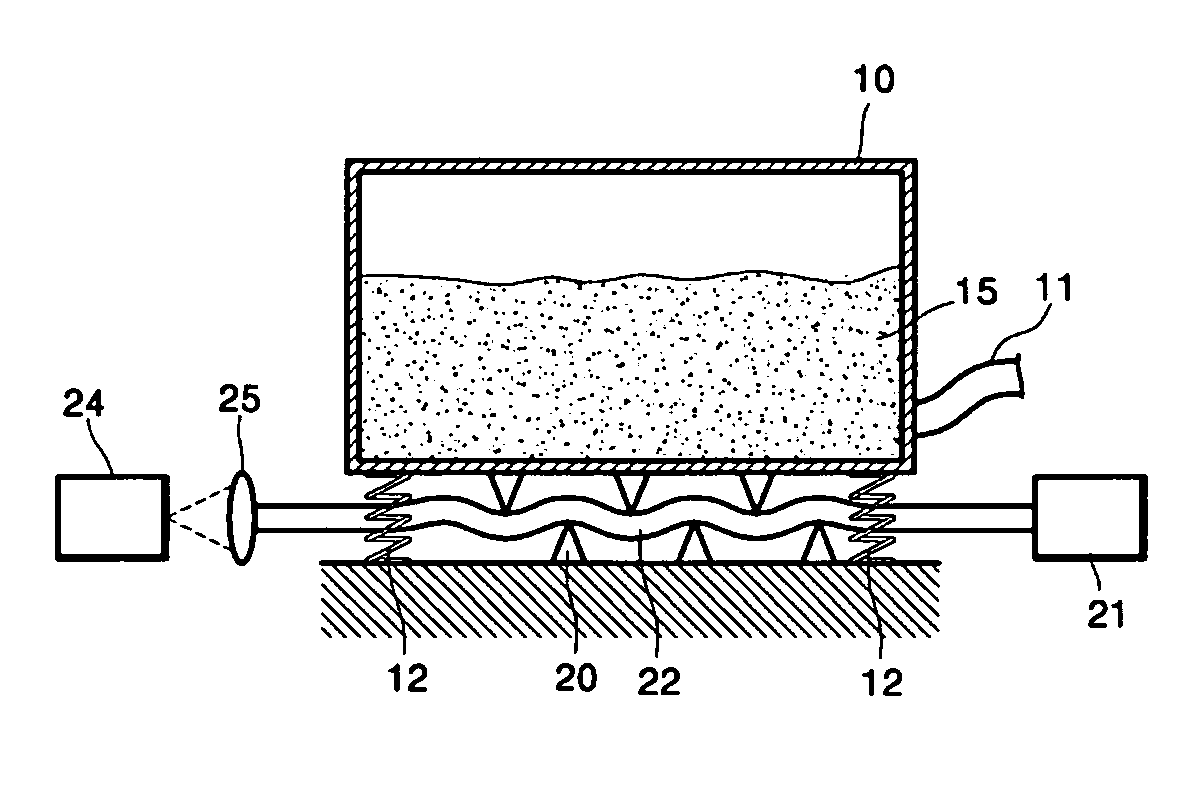
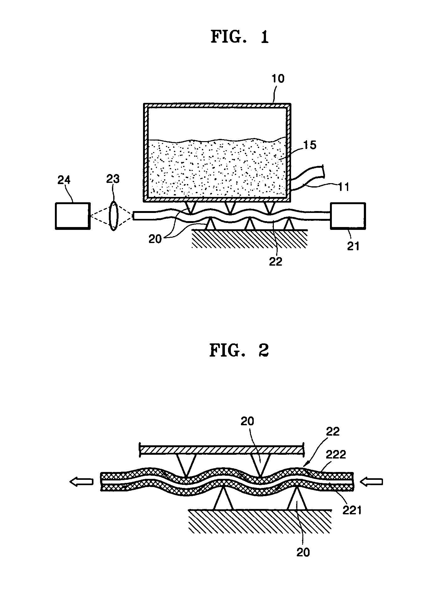
[0033]FIG. 1 is a view of an ink level detecting apparatus according to an embodiment of the present general inventive concept. An ink tank 10 stores ink and has an ink outlet 11 at a bottom portion thereof. The ink outlet 11 is connected to an ink ejection unit (not shown) via a flexible tube to minimize an external force applied to the ink tank 10.

[0034] An optical fiber 22 is disposed below the ink tank 10, and a pressuring unit 20 to bend the optical fiber 22 according to the weight of the ink tank 10 are disposed near the optical fiber. The pressuring unit 20 may include a plurality of upper protrusions that protrude from the bottom surface of the ink tank 10 and a plurality of lower protrusions protruding fro...


PUM


Abstract

An ink level detecting apparatus usable with an inkjet printer, which uses an optical fiber to detect the ink level. The ink level detecting apparatus includes: an ink tank having an ink outlet; an optical fiber disposed near the ink tank; a light source which is disposed at a front end of the optical fiber and emits light; a light receiving sensor which is disposed at a rear end of the optical fiber and senses light propagating through the optical fiber; and a pressuring unit which presses the optical fiber so as to bend the optical fiber according to the weight of the ink tank.

Description

CROSS-REFERENCE TO RELATED APPLICATIONS [0001] This application claims the priority of Korean Patent Application No. 2005-64066, filed on Jul. 15, 2005 in the Korean Intellectual Property Office, the disclosure of which is incorporated herein in its entirety by reference. BACKGROUND OF THE INVENTION [0002] 1. Field of the Invention [0003] The present general inventive concept relates to an ink level detecting apparatus usable with an inkjet printer, and more particularly, to an ink level detecting apparatus that can continuously detect in real time the level of ink remaining in an ink tank using an optical fiber. [0004] 2. Description of the Related Art [0005] Generally, in an inkjet printer, ink contained in an ink tank is supplied via a predetermined ink supply path to an ink ejecting unit having ink ejecting heads, and then the ink is ejected in micro droplets via the ink ejecting heads. Therefore, as the inkjet printer performs a printing job, the level of ink remaining inside t...

Claims


Application Information

Patent Timeline
IPC IPC(8): B41J2/195B41J29/393B41J2/175
CPCB41J2/17566
Inventor JUNG, SUNG-JUNE
Owner SAMSUNG ELECTRONICS CO LTD
Why Eureka
Try Eureka