Image-processing apparatus and image-pickup apparatus

a technology of image processing and pick-up apparatus, which is applied in the direction of color signal processing circuits, color television details, television systems, etc., can solve the problems of inability to accurately sample period equivalents. , to achieve the effect of eliminating flickers, high reliability, and enhanced performan

Active Publication Date: 2007-01-18
SONY CORP
View PDF11 Cites 30 Cited by
  • Summary
  • Abstract
  • Description
  • Claims
  • Application Information

AI Technical Summary

Benefits of technology

[0026] In accordance with an image-processing apparatus according to an embodiment of the present invention, an interpolation process is carried out on the basis of integration values output by integration means in order to generate integration values corresponding to a predetermined number of sampling positions for a period of flickers or a plurality of periods of flickers. Thus, a predetermined number of integration values sampled in a period of flickers or a plurality of periods of flickers can be output with a high degree of reliability independently of the number of lines included in the image signal and the screen rate. As a result, it is possible to implement an image-processing apparatus having enhanced performance to eliminate flickers and good versatility.
[0027] In addition, in accordance with an image-processing apparatus according to another embodiment of the present invention, an interpolation process is carried out on the basis of normalized integration or difference values output by normalization means in order to generate pieces of data corresponding to a predetermined number of sampling positions set in advance during a period of flickers or a plurality of periods of flickers. Thus, a predetermined number of pieces of data sampled in a period of flickers or a plurality of periods of flickers can be supplied to frequency analysis means with a high degree of reliability independently of the number of lines included in the image signal and the screen rate. As a result, it is possible to implement an image-processing apparatus having enhanced performance to eliminate flickers and good versatility.
[0028] On top of that, in accordance with an image-processing apparatus according to a further embodiment of the present invention, an interpolation process is carried out on the basis of values extracted in a frequency analysis process as discrete values of a flicker component in order to generate a predetermined number of pieces of data during a period of flickers or a plurality of periods of the flicker component included in an image signal as pieces of data each prescribed to have an output timing synchronized with the period of an integration unit used by the integration means or synchronized with the period of a multiple of the integration unit. Then, on the basis of the generated pieces of data, an image signal is corrected. Thus, the phase of an inferred value of a flicker waveform representing the flicker component, discrete values of which are used as the basis of the interpolation process, can be adjusted to match the phase of the image signal supplied to image correction means as a signal to be corrected, allowing the number of errors generated in a process to correct the image signal to be reduced independently of the number of lines included in the image signal and the screen rate. As a result, it is possible to implement an image-processing apparatus having enhanced performance to eliminate flickers and good versatility.
[0029] In addition, in accordance with an image-processing apparatus according to a still further embodiment of the present invention, an interpolation process is carried out by using discrete values of correction parameters computed on the basis of values extracted in a frequency analysis process as inferred values of a flicker component in order to generate a predetermined number of pieces of data during a period of flickers or a plurality of periods of the flicker component included in an image signal as pieces of data each prescribed to have an output timing synchronized with the period of an integration unit used by the integration means or synchronized with the period of a multiple of the integration unit. Then, the pieces of data generated as interpolated correction parameters are supplied to image correction means. Thus, the phase of the correction parameter computed on the basis of inferred values of a flicker component can be adjusted to match the phase of the image signal supplied to the image correction means as a signal to be corrected, allowing the number of errors generated in a process to correct the image signal to be reduced independently of the number of lines included in the image signal and the screen rate. As a result, it is possible to implement an image-processing apparatus having enhanced performance to eliminate flickers and good versatility.

Problems solved by technology

In consequence, if the integration values obtained for all the lines in a process to sample one period of a flicker waveform are all used, the size of a processing circuit including a memory for storing the integration values and a DFT processing circuit also rises inevitably.
If a line is sampled by thinning the line at a fixed rate of L / L1, however, it is no longer possible to accurately sample a period equivalent to one period of a flicker waveform unless the value of L / L1 is an integer.
Thus, a detection error is inevitably generated.

Method used


Image

  • Image-processing apparatus and image-pickup apparatus
  • Image-processing apparatus and image-pickup apparatus
  • Image-processing apparatus and image-pickup apparatus

Examples


first embodiment

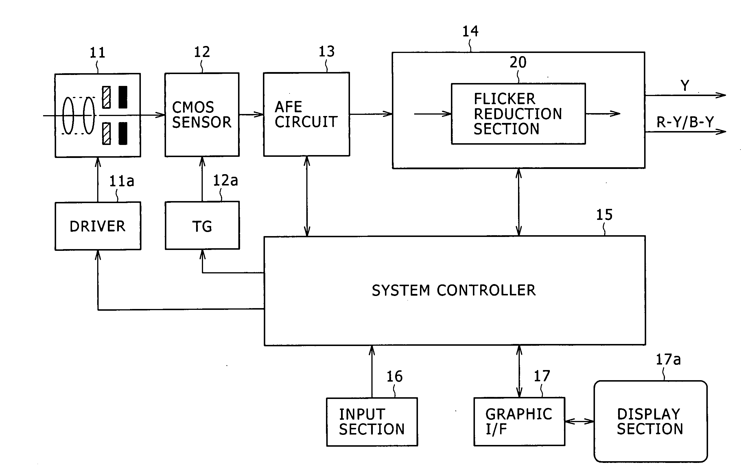
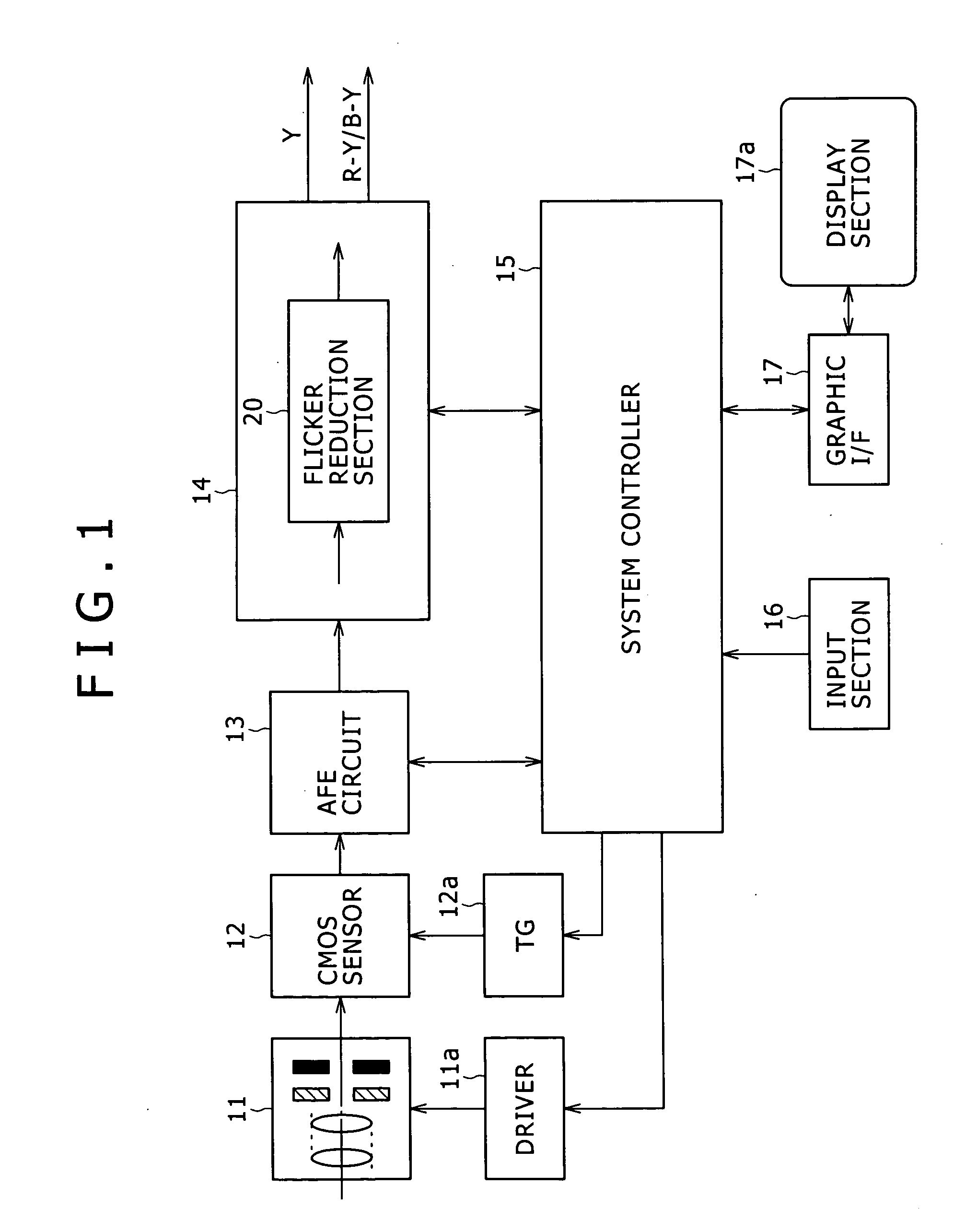
[0054]FIG. 1 is a block diagram showing a configuration including components composing an image-pickup apparatus according to the first embodiment of the present invention.

[0055] The image-pickup apparatus shown in FIG. 1 has an optical block 11, a driver 11a, a CMOS image sensor 12, a time generator (TG) 12a, an analog front end (AFE) circuit 13, a camera processing circuit 14, a system controller 15, an input section 16, a graphic interface (I / F) 17 and a display section 17a. In the following description, the CMOS image sensor 12 is referred to simply as a CMOS sensor.

[0056] The optical block 11 includes a lens, a lens driving mechanism, a shutter mechanism and an iris mechanism. The lens has a function to focus light coming from an object of photographing on the CMOS sensor 12. The lens driving mechanism is a mechanism for moving the lens in order to adjust the focus and carry out a zooming process. The driver 11a controls operations to drive the mechanisms in the optical block...

second embodiment

[0149]FIG. 15 is a block diagram showing a typical internal configuration of a flicker reduction section 20a according to a second embodiment of the present invention. It is to be noted that, in the typical configuration shown in FIG. 15, components identical with their counterparts of the configuration shown in FIG. 3 are denoted by the same reference numerals as the counterparts and description of the components is not given.

[0150] In the second embodiment shown in FIG. 15, much like the first embodiment described earlier, instead of carrying out an interpolation process to produce pieces of data at L1 points accurately corresponding to a period with a length equal to a period (or a plurality of periods) of the flicker wavelength from integration values generated by the line integrator 210, an interpolation process is carried out. Then, the process generates pieces of sampling data accurately corresponding to a period with a length equal to a period (or a plurality of periods) of...

third embodiment

[0157]FIG. 16 is a block diagram showing a typical internal configuration of a flicker reduction section 20b according to a third embodiment of the present invention. It is to be noted that, in the typical configuration shown in FIG. 16, components identical with their counterparts of the configuration shown in FIG. 15 are denoted by the same reference numerals as the counterparts and description of the components is not given.

[0158] The flicker reduction section 20b shown in FIG. 16 is different from the internal configuration of the flicker reduction section 20a shown in FIG. 15 in that, in the case of the flicker reduction section 20b, an inferred-component interpolation section 160 is provided between the flicker generation section 130 and the processing section 140 as a substitute for the flicker-component interpolation section 150. In the configuration of the flicker reduction section 20b, flicker components (or, strictly speaking, the flicker coefficient Γn (y)) inferred in ...


PUM


Abstract

An image-processing apparatus includes an integration section to integrate an image signal in more than one unit of horizontal synchronization period; an interpolation section to carry out an interpolation on the basis of integration values output by the integration section in order to generate integration values corresponding to a predetermined number of sampling positions set in advance during at least one period of flickers appearing on a screen under a fluorescent lamp; a normalization section to normalize an integration value output by the interpolation section or to normalize a difference value between integration values output by the interpolation section as integration values for adjacent fields or frames, respectively; a frequency analysis section to extract a spectrum of normalized integration value or difference values output by the normalization section; and a flicker inference section to infer a flicker component from the spectrum extracted by the frequency analysis section.

Description

CROSS-REFERENCE TO RELATED APPLICATIONS [0001] The present application claims priority from Japanese Patent Application Nos. JP 2005-172109, filed on Jun. 13, 2005, and JP 2005-325268, filed on Nov. 9, 2005, the disclosures of which are hereby incorporated by reference herein. BACKGROUND OF THE INVENTION [0002] The present invention relates to an image-processing apparatus for processing an image signal and an image-pickup apparatus having the function of the image-processing apparatus. More particularly, the present invention relates to an image-processing apparatus suitable for processing of an image signal representing an image taken by using a solid-state image-pickup device of an XY address scanning type and relates to an image-pickup apparatus having the function of such an image-processing apparatus. [0003] When an object of photographing is photographed in illumination of a blinking light source such as a fluorescent lamp driven by a commercial alternating-current power supp...

Claims


Application Information

Patent Timeline
Patent Type & Authority Applications(United States)
IPC IPC(8): H04N5/228H04N5/232H04N5/235H04N5/335H04N5/341H04N5/345H04N5/351H04N5/357H04N5/374
CPCH04N5/2357H04N5/235H04N23/70H04N23/745H04N23/00
Inventor KINOSHITA, MASAYAINABA, SEIJIROGOMI, KEIZO
Owner SONY CORP
Why Eureka
Try Eureka