Evaluating device, reproducing device, and evaluating method

a technology of reproducing device and evaluation value, which is applied in the direction of amplitude demodulation, instruments, recording signal processing, etc., can solve the problems of affecting the calculation efficiency of the evaluation value, so as to achieve the effect of simplifying the calculation of the evaluation valu

Inactive Publication Date: 2007-01-18
SONY CORP
View PDF2 Cites 34 Cited by
  • Summary
  • Abstract
  • Description
  • Claims
  • Application Information

AI Technical Summary

Benefits of technology

[0049] Further, according to the above-described present invention, in obtaining the evaluation index that reflects the rate of contribution of each error pattern to the to

Problems solved by technology

However, it is difficult to achieve this with a simple configuration because Equation 1 requires such a complex calculation as uses a mathematical table, rather than an

Method used


Image

  • Evaluating device, reproducing device, and evaluating method
  • Evaluating device, reproducing device, and evaluating method
  • Evaluating device, reproducing device, and evaluating method

Examples


first embodiment

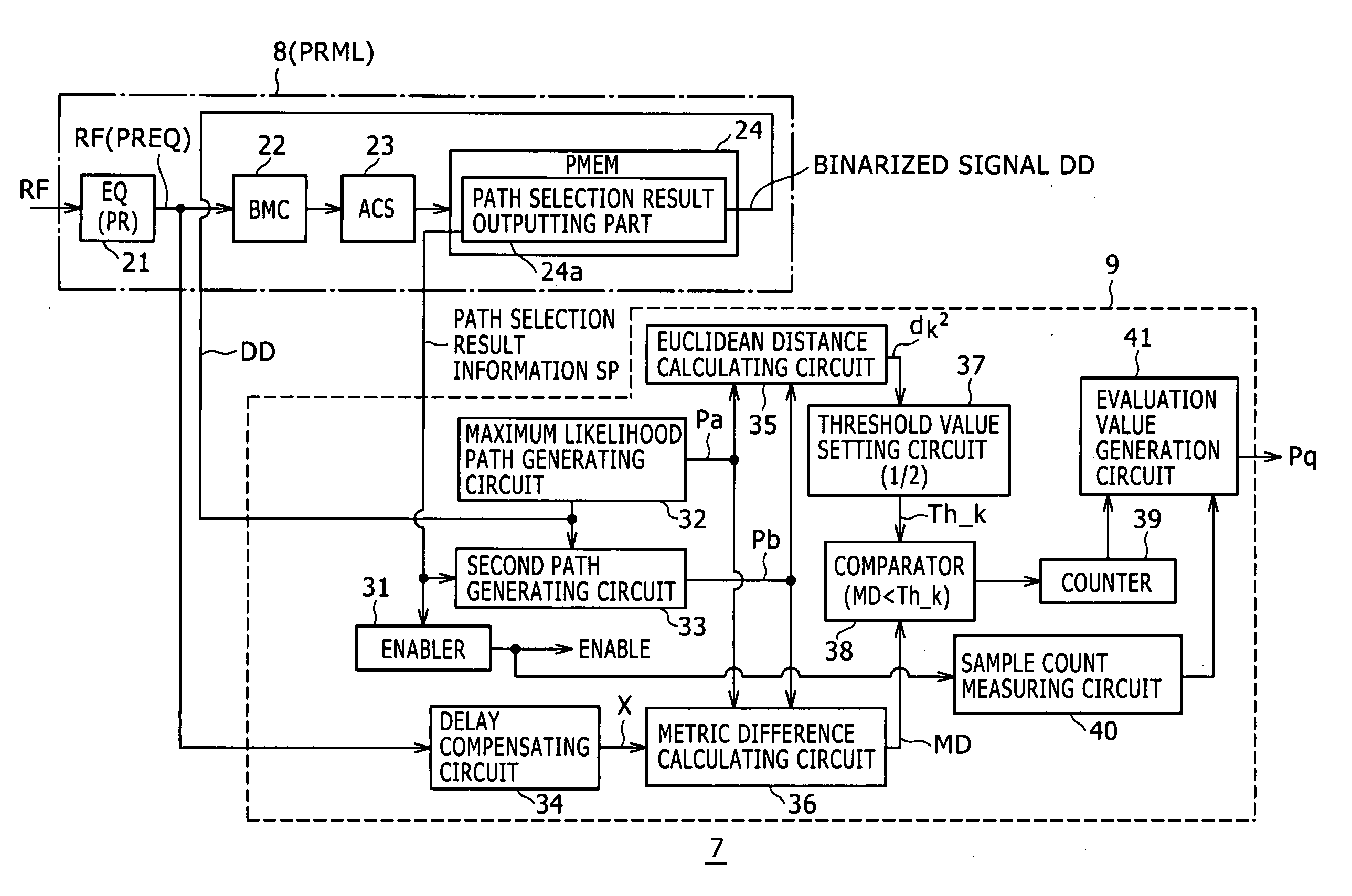
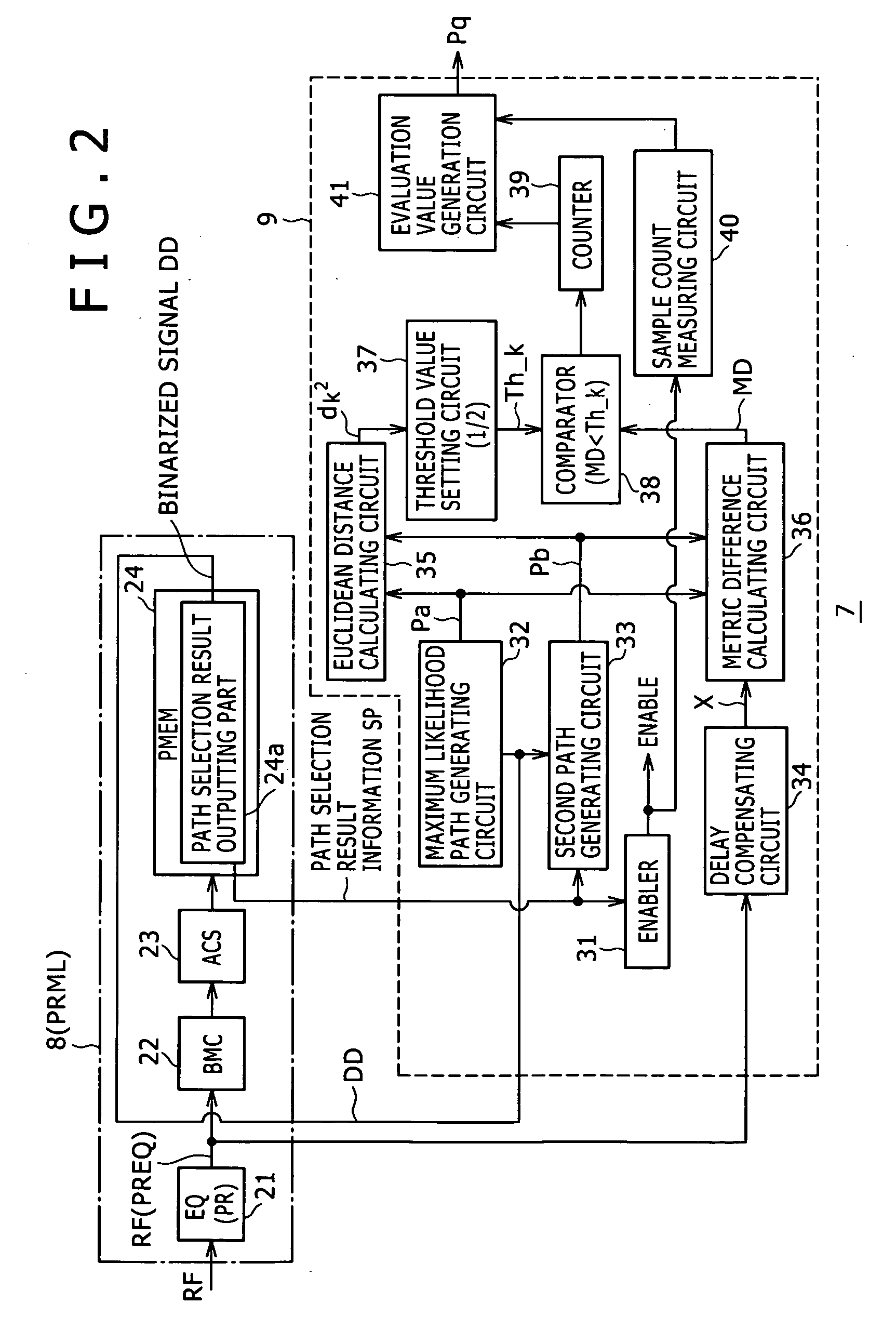
[0093] The path memory updating unit24 in the first embodiment is provided with a path selection result outputting part 24a for outputting the information on the bit sequences of the maximum likelihood path and the second path as path selection result information SP.

[0094] The path selection result information SP output by the path selection result outputting part 24a is supplied to an enabler 31 and the second path generating circuit 33 to be described later within the signal evaluating circuit 9.

[0095] As is understood from the above-described configuration of the PRML decoder 8, a method of bit detection by PRML is an algorithm that compares the magnitudes of a Euclidean distance between a partial response sequence obtained from a correct bit sequence and the reproduced signal RF (that is, a path metric for the correct bit sequence) and a Euclidean distance between a partial response sequence obtained from an erroneous bit sequence and the reproduced signal RF (that is, a path m...

second embodiment

[0190] the present invention will next be described.

[0191]FIG. 7 is a block diagram showing an internal configuration of an evaluating device 7 according to the second embodiment.

[0192] While in the foregoing first embodiment, the path selection result information SP indicating an actual path selection result is referred to to identify an error pattern between a maximum likelihood path Pa and a second path Pb, the second embodiment identifies the error pattern on the basis of a pattern table.

[0193] Incidentally, in FIG. 7, parts already described in the first embodiment are identified by the same reference numerals, and description thereof will be omitted. Description will principally be made of only differences.

[0194] In a PRML decoder 8 in this case, the path selection result outputting part 24a provided in the path memory updating unit 24 is omitted.

[0195] A signal evaluating circuit 9 is provided with a pattern detecting circuit and pattern table 50 shown in FIG. 7. The patt...

third embodiment

[0207] Accordingly, a third embodiment proposes a configuration of an evaluating device 7 corresponding to a case where a configuration of such an adaptive type Viterbi detector is employed.

[0208] An outline of such an adaptive type Viterbi technology will first be described with reference to FIGS. 9A and 9B.

[0209]FIGS. 9A and 9B show relation between reference levels set in a Viterbi detector (PRML detector 8) and a reproduced signal (eye pattern) when PR(1, 2, 2, 1), for example, is employed as a partial response type.

[0210]FIG. 9A shows a case where the amplitude levels in the reproduced signal of mark lengths corresponding respectively to the reference levels (R-Lva to R-Lvg in the figure) in PR employed by the Viterbi detector are ideal levels expected in the PR type.

[0211] On the other hand, FIG. 9B shows a case where a sufficient amplitude cannot be obtained for a reproduced signal of a shortest mark length, in particular, as for example the recording density of the record...


PUM


Abstract

An evaluating device including: a Viterbi detector to perform bit detection by Viterbi detection from a reproduced signal in which bit information is reproduced; a metric difference calculator to calculate a metric difference between values of path metrics for a second path and a maximum likelihood path when at least an error pattern between the maximum likelihood path as a path surviving as a result of path selection by the Viterbi detector and the second path compared finally with the maximum likelihood path corresponds to one of a predetermined plural error patterns; and an evaluation value calculator to compare each of values of metric differences calculated by the metric difference calculator for each error pattern, with an individual threshold value obtained by dividing a Euclidean distance between the maximum likelihood path and the second path in each error pattern by a common value, and calculate a total number of values of the metric differences less than the threshold value as an evaluation value.

Description

CROSS REFERENCES TO RELATED APPLICATIONS [0001] The present invention contains subject matter related to Japanese Patent Application JP 2005-200235 filed in the Japanese Patent Office on July 8, 2005, the entire contents of which being incorporated herein by reference. BACKGROUND OF THE INVENTION [0002] 1. Field of the Invention [0003] The present invention relates to an evaluating device suitable for a case where PRML (Partial Response Maximum Likelihood) decoding processing is performed on a reproduced signal from a recording medium, for example, a reproducing apparatus that includes such an evaluating device and reproduces information recorded on a recording medium, and an evaluating method. [0004] 2. Description of the Related Art [0005] For example, as a method for evaluating signal quality of a reproduced signal from an optical disk, a method of evaluating time interval jitter (TI jitter) is known. TI jitter refers to variations (jitter) in time difference (time interval) betw...

Claims


Application Information

Patent Timeline
IPC IPC(8): H03D1/00H03M13/03H04B1/10
CPCG11B20/10009G11B20/10046G11B20/10055G11B20/10111G11B20/1012H04L25/03191G11B20/10481G11B20/1816H03M13/41H03M13/612G11B20/10296
Inventor SHIRAISHI, JUNYA
Owner SONY CORP
Why Eureka
Try Eureka