Check patentability & draft patents in minutes with Patsnap Eureka AI!

Moving-object tracking control apparatus, moving-object tracking system, moving-object tracking control method, and program

a technology of moving objects and control apparatus, applied in the direction of television systems, instruments, image enhancement, etc., can solve the problems of less stable determination processing and processing time, and achieve the effect of stable moving object tracking process

Inactive Publication Date: 2007-01-18
SONY CORP
View PDF5 Cites 31 Cited by
  • Summary
  • Abstract
  • Description
  • Claims
  • Application Information

AI Technical Summary

Benefits of technology

[0015] The first problem relates to the processing time. In this detection method, motion vectors are determined for not only a target to be tracked but also its surrounding area. In addition, the larger the size of the target to be tracked, the more the motion vectors are to be determined for the area surrounding the target to be tracked. The processing time therefore increases.
[0032] Further, the local motion vectors are continuously calculated only for the calculation points positioned in the moving-object region. Thus, even if another moving object approaches close to the moving target being tracked, the calculation of the local motion vectors can be continuously performed without being affected by the moving object. Therefore, a stable moving-object tracking process can be achieved.

Problems solved by technology

However, this detection method has the following two problems.
The first problem relates to the processing time.
The second problem is that the determination processing becomes less stable when, as shown in FIG. 2, a moving object exists near the target to be tracked.

Method used


Image

  • Moving-object tracking control apparatus, moving-object tracking system, moving-object tracking control method, and program
  • Moving-object tracking control apparatus, moving-object tracking system, moving-object tracking control method, and program
  • Moving-object tracking control apparatus, moving-object tracking system, moving-object tracking control method, and program

Examples


first embodiment

Overall Structure of Moving-Object Tracking System

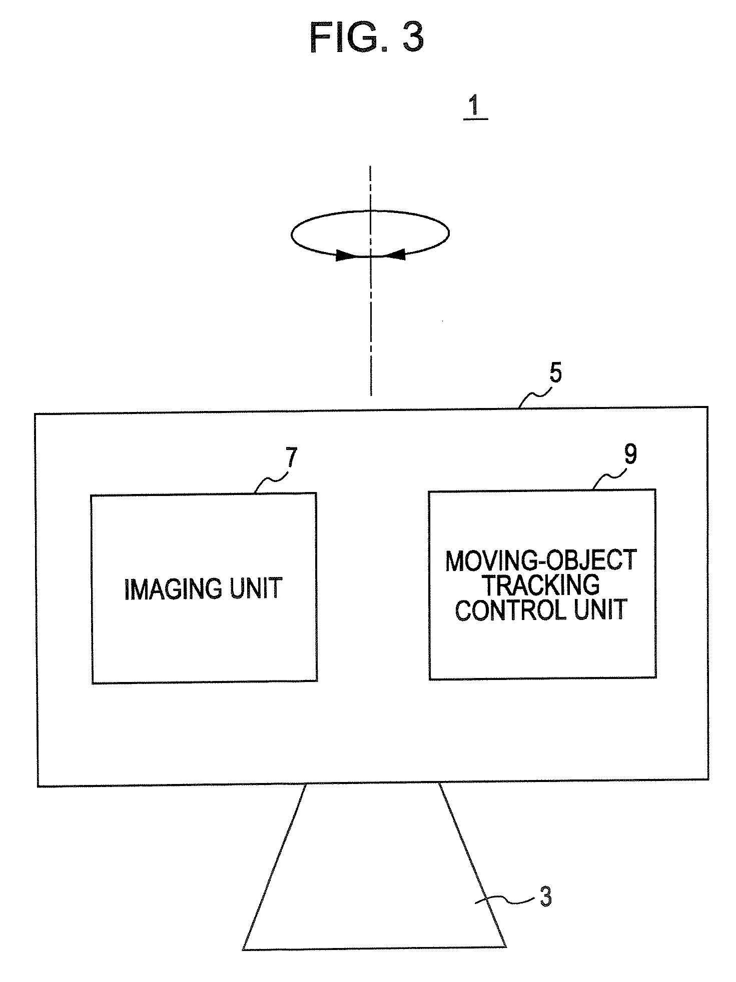
[0056]FIG. 3 shows an example structure of a moving-object tracking system 1 according to a first embodiment of the present invention. The moving-object tracking system 1 is a system in which an imaging apparatus 5 mounted on a rotating stage 3 (movable mechanism) includes a moving-object tracking control apparatus. The rotating stage 3 and the imaging apparatus 5 may be integrally formed or removably attached to each other.

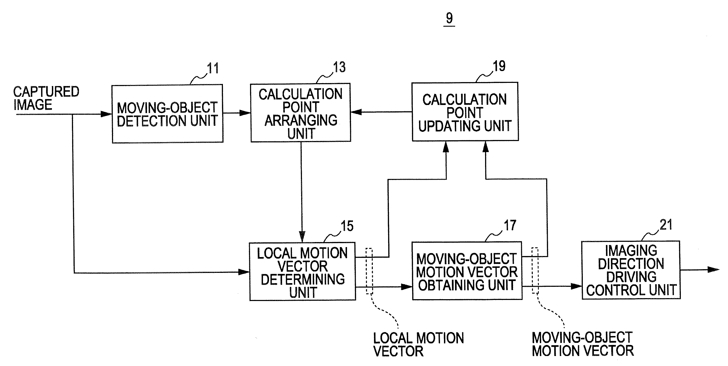
[0057] The imaging apparatus 5 includes an imaging unit 7 and a moving-object tracking control unit (hereinafter also referred to as a “moving-object tracking control apparatus”) 9. The imaging unit 7 is formed of an imaging device, such as a charge-coupled device (CCD) sensor or a complementary metal oxide semiconductor (CMOS) sensor, an optical lens, and other components.

[0058] The rotating stage 3 is a movable mechanism capable of driving the imaging apparatus 5 mounted thereon so that the imaging direction...

second embodiment

[0102] In the first embodiment, only the rotation of the imaging apparatus is controlled based on the detected moving-object motion vector.

[0103] In a situation where an intruder is monitored using a moving-object tracking system, once a moving object is initially detected (in a moving-object detection mode), the lens of the imaging apparatus is often set to the wide-angle position to monitor a wide range. When the detected intruder is tracked, on the other hand, the lens of the imaging apparatus is zoomed in to show the intruder at a larger size in order to provide a detailed image of the intruder.

[0104] Further, as the intruder moves closer to or farther from the imaging apparatus, it is necessary to adjust the zoom of the lens of the imaging apparatus by zoom in or out to provide the image of the intruder with the desired size.

[0105] For example, in FIGS. 13A and 13B, a change in images captured when an intruder moves farther from the photographer for a period from time t1 to ...


PUM


Abstract

A moving-object region is specified on an image captured by an imaging apparatus, and a plurality of calculation points are arranged on the specified region. A group of local motion vectors is determined for the calculation points, and a moving-object motion vector is obtained based on the determined local motion vectors. A group of calculation points whose local motion vectors are the same as or similar to the moving-object motion vector is continuously used to calculate the local motion vectors, and is updated by moving the position of the group of calculation points along the moving-object motion vector, and a calculation point whose local motion vector is different from the moving-object motion vector is rearranged by placing a new calculation point at a position near any of the continuously used calculation points. A movable mechanism including the imaging apparatus is controlled in accordance with the moving-object motion vector.

Description

CROSS REFERENCES TO RELATED APPLICATIONS [0001] The present invention contains subject matter related to Japanese Patent Application JP 2005-206339 filed in the Japanese Patent Office on Jul. 15, 2005, the entire contents of which are incorporated herein by reference. BACKGROUND OF THE INVENTION [0002] 1. Field of the Invention [0003] An embodiment of the present invention relates to a moving-object tracking control apparatus for controlling tracking of a moving object moving on a screen. Another embodiment of the present invention relates to a system including the moving-object tracking control apparatus. [0004] A further embodiment of the present invention relates to a method and program for implementing the moving-object tracking control function. [0005] 2. Description of the Related Art [0006] In monitoring systems, the capability (tracking capability) of tracking a moving target (e.g., a person, a vehicle, or other objects) through images on the screen captured by an imaging ap...

Claims


Application Information

Patent Timeline
Patent Type & Authority Applications(United States)
IPC IPC(8): G06K9/00
CPCG01S3/7864G06K9/00369G06T2207/30241G06T7/2006G06T7/2033G06K9/00771G06T7/215G06T7/246G06V40/103G06V20/52
Inventor TSUNASHIMA, NOBUHIRO
Owner SONY CORP
Features
  • R&D
  • Intellectual Property
  • Life Sciences
  • Materials
  • Tech Scout
  • Unparalleled Data Quality
  • Higher Quality Content
  • 60% Fewer Hallucinations
Learn More