
Control apparatus and control method of an automatic transmission

a technology of automatic transmission and control apparatus, which is applied in the direction of gearing control, belt/chain/gearing, gearing element, etc., can solve the problems of tie-up in the automatic transmission b>10/b>

Inactive Publication Date: 2007-01-18
TOYOTA JIDOSHA KK
View PDF5 Cites 37 Cited by
  • Summary
  • Abstract
  • Description
  • Claims
  • Application Information

AI Technical Summary

Benefits of technology

[0008] In view of the foregoing problems, this invention thus provides a control apparatus and control method of an automatic transmission that establishes a plurality of speeds of different speed ratios by selectively engaging and / or releasing a plurality of engagement devices, and which prevents the engine speed from exceeding a predetermined maximum allowable speed when preventing tie-up in the automatic transmission which arises from abnormal engagement of an engagement device.
[0009] Therefore, one aspect of the invention relates to a control apparatus of an automatic transmission that establishes a plurality of speeds of different speed ratios by selectively engaging and / or releasing a plurality of engagement devices. This control apparatus includes an abnormal engagement detector that detects abnormal engagement of at least one of the engagement devices which causes tie-up to occur in the automatic transmission; and a controller that establishes a predetermined specific speed set in advance in order to prevent tie-up from occurring in the automatic transmission, when abnormal engagement of the at least one of the engagement devices is detected by the abnormal engagement detector, and places the automatic transmission in a neutral state when an engine speed will exceed a predetermined allowable speed if the predetermined specific speed is established.
[0011] According to the control apparatus and control method of an automatic transmission described above, in an automatic transmission which establishes a plurality of speeds of different speed ratios by selectively engaging and / or releasing a plurality of engagement devices, when abnormal engagement of at least one of the engagement devices which causes tie-up to occur in the automatic transmission is detected and the engine speed will exceed the predetermined allowable speed if the predetermined specific speed set in advance is established in order to prevent that tie-up from occurring, the automatic transmission is placed in a neutral state. As a result, tie-up that arises from abnormal engagement of an engagement device is prevented from occurring in the automatic transmission. In addition, a case in which the engine speed exceeds the predetermined allowable engine speed due to the predetermined specific speed being established, i.e., in which overrun that accompanies the shift into the predetermined specific speed occurs, can be avoided.
[0016] Also, the power source for running the vehicle is preferably drivingly connected to an input rotating member of the automatic transmission via a fluid power transmitting device or a lockup clutch or the like. A torque converter with a lockup clutch or a fluid coupling may be used as the fluid power transmitting device. Further, an engine which is an internal combustion engine such as a gasoline engine or a diesel engine may be used as the power source for running the vehicle. Moreover, an electric motor or the like may also be used, in addition to the engine, in a power transmission path between the engine and the driven wheels as a power source to assist with running.

Problems solved by technology

More specifically, if an engagement device is unable to release due to a problem with, for example, a shift control valve that controls the engagement operation of the engagement device, it may cause tie-up to occur in the automatic transmission 10.

Method used


Image

  • Control apparatus and control method of an automatic transmission
  • Control apparatus and control method of an automatic transmission
  • Control apparatus and control method of an automatic transmission

Examples


Embodiment Construction

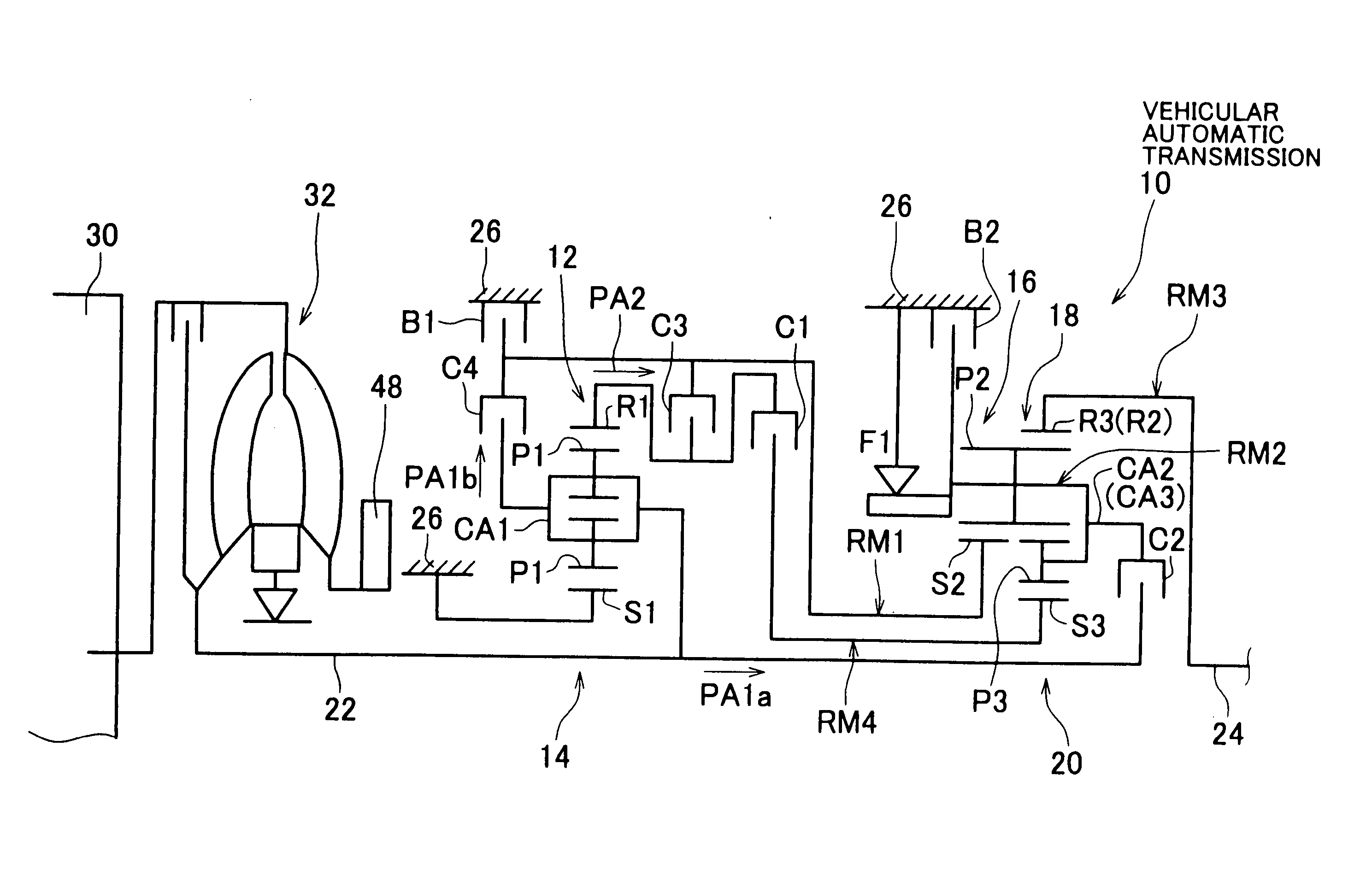
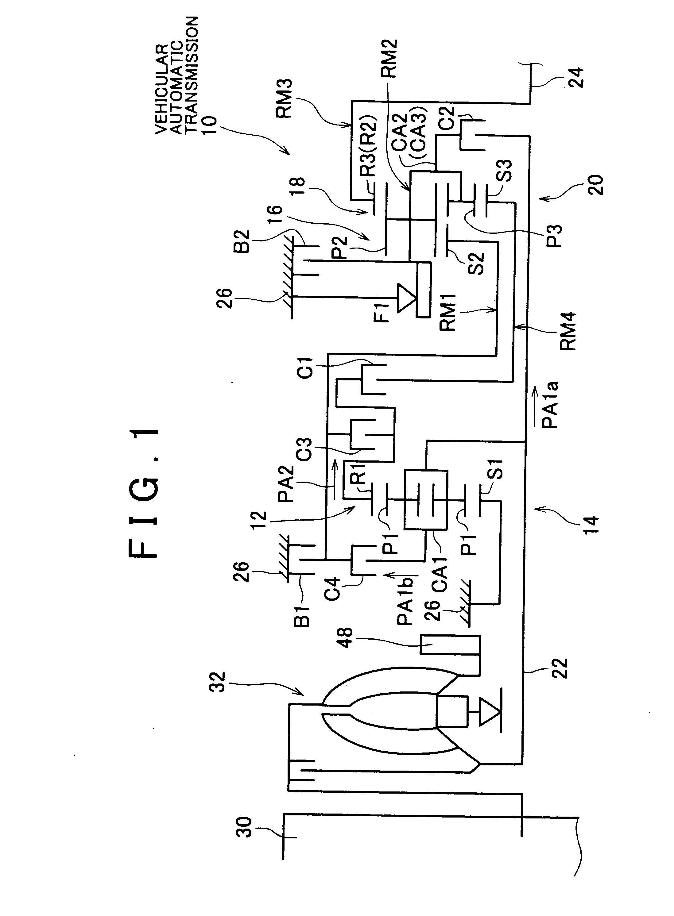
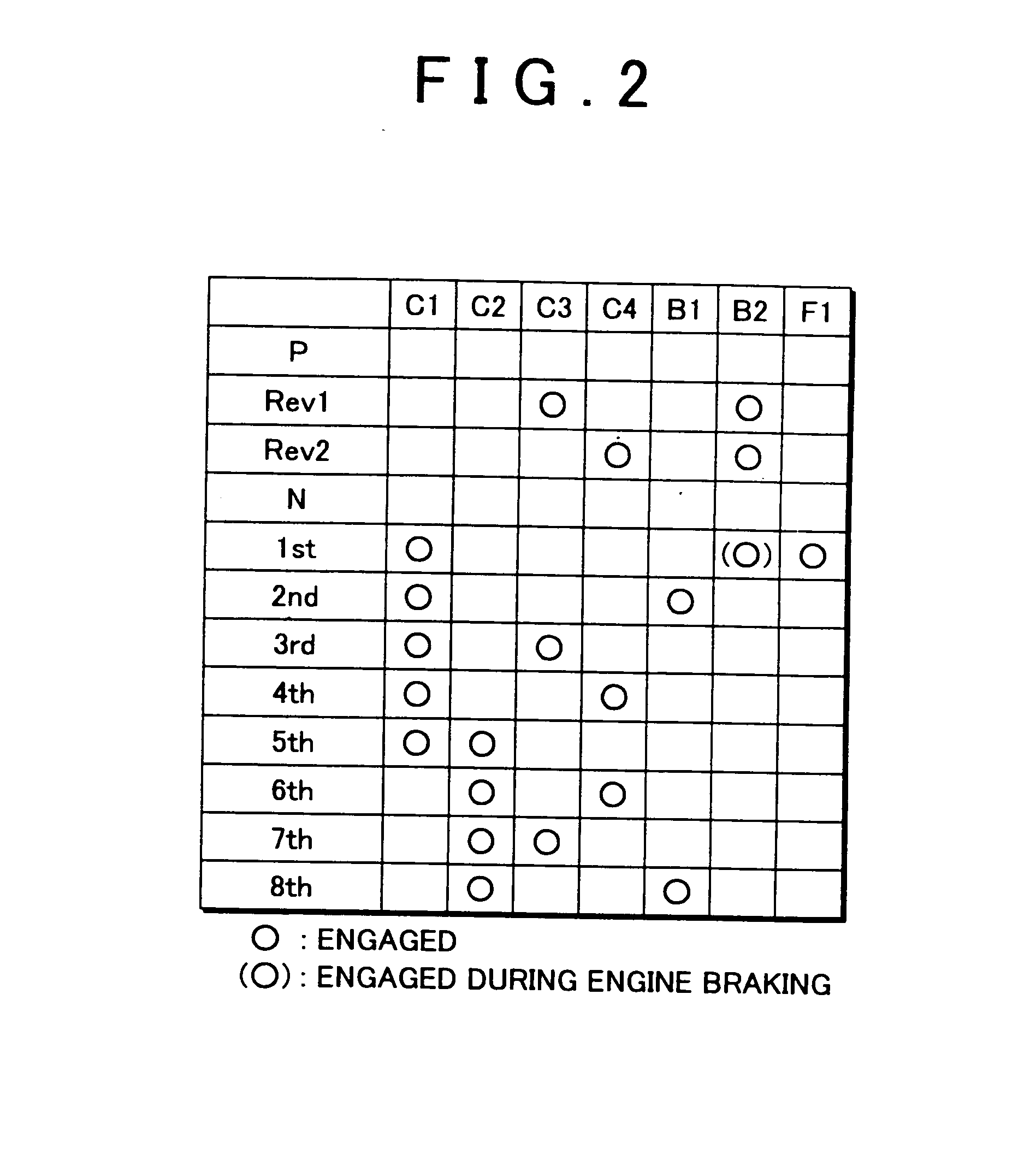
[0027] In the following description and the accompanying drawings, the present invention will be described in more detail with reference to exemplary embodiments. FIG. 1 is a skeleton view illustrating the structure of an automatic transmission 10 for a vehicle to which the invention has been applied. FIG. 2 is a clutch and brake engagement chart showing various engagement and release combinations of engagement devices (engagement elements) to achieve a plurality of speeds in the automatic transmission 10. The automatic transmission 10 includes a first transmitting portion 14 and a second transmitting portion 20 aligned on the same axis within a transmission case (hereinafter simply referred to as “case”) 26 which is a non-rotating member that is attached to the vehicle body. The first transmitting portion 14 mainly includes a double pinion type first planetary gearset 12, while the second transmitting portion 20 mainly includes a single pinion type second planetary gearset 16 and a...


PUM


Abstract

A control apparatus and control method of an automatic transmission that establishes a plurality of speeds of different speed ratios by selectively engaging and / or releasing a plurality of engagement devices, detects abnormal engagement of at least one of the engagement devices which causes tie-up to occur in the automatic transmission; establishes a predetermined specific speed set in advance in order to prevent tie-up from occurring in the automatic transmission, when abnormal engagement of the at least one of the engagement devices is detected; and places the automatic transmission in a neutral state when an engine speed will exceed a predetermined allowable speed if the predetermined specific speed is established.

Description

INCORPORATION BY REFERENCE [0001] The disclosure of Japanese Patent Application No. 2005-203850 filed on Jul. 13, 2005, including the specification, drawings and abstract is incorporated herein by reference in its entirety. BACKGROUND OF THE INVENTION [0002] 1. Field of the Invention [0003] The invention relates to a control apparatus and control method of a vehicular automatic transmission. More particularly, the invention relates to control of an automatic transmission when tie-up occurs in the automatic transmission. [0004] 2. Description of the Related Art [0005] Vehicles provided with an automatic transmission in which a shift is executed by selectively engaging a plurality of engagement devices are well known. For example, the vehicle is described in Japanese Patent Application Publication No. JP-A-2000-65203 is one such vehicle. Japanese Patent Application Publication No. JP-A-2000-65203 discloses a control apparatus of an automatic transmission which prevents tie-up (i.e., d...

Claims


Application Information

Patent Timeline
IPC IPC(8): B60W10/04F16H59/42F16H59/68F16H61/12F16H61/68F16H61/684F16H61/686
CPCF16H61/12F16H61/686F16H2061/1232F16H2061/1204Y10T477/60Y10T477/69373Y10T477/69364Y10T477/6934F16H2061/168
Inventor OTA, HIROFUMIABE, AKIHARUHONDA, ATSUSHINOZAKI, KAZUTOSHI
Owner TOYOTA JIDOSHA KK
Learn More