Memory control apparatus and method

a memory control and memory technology, applied in the field of memory control apparatus and methods, can solve the problems of increasing circuit scale and chip cost, increasing heat, and reducing reliability, and achieve the effect of suppressing the increase in memory access latency of each master and reducing the capacity of buffer fifo

Active Publication Date: 2007-01-18
CANON KK
View PDF17 Cites 121 Cited by
  • Summary
  • Abstract
  • Description
  • Claims
  • Application Information

AI Technical Summary

Benefits of technology

[0032] It is an object of the present invention to decrease the capacity of a buffer FIFO by suppressing an in

Problems solved by technology

This increases the circuit scale and chip cost.
In addition, various adverse effects such as an increase in heat and a decrease in reliability occur.
This configuration cannot be used when data must continuously be supplied to the printer engine once the printer operation starts, like the above-described printer controller.
However, if another master has

Method used


Image

  • Memory control apparatus and method
  • Memory control apparatus and method
  • Memory control apparatus and method

Examples


first embodiment

[0053] the present invention will be described below in detail with reference to the accompanying drawings.

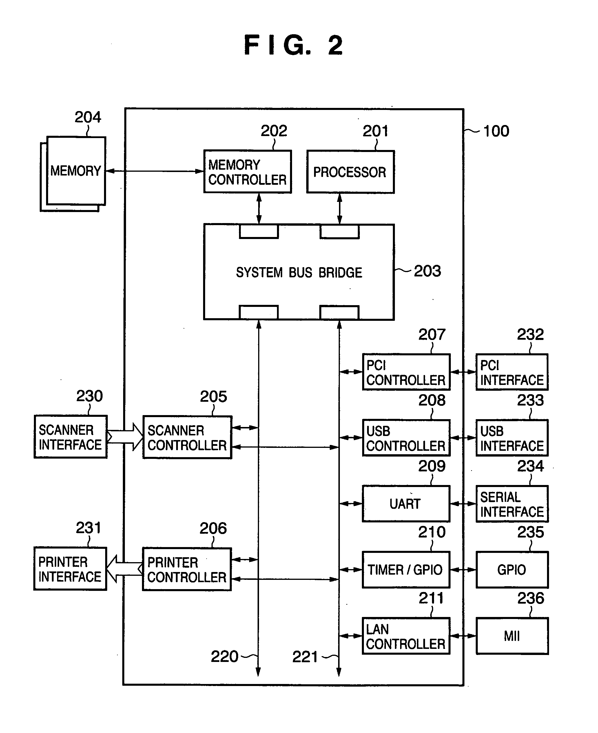
[0054]FIG. 8 is a block diagram for explaining the first embodiment of the present invention. Referring to FIG. 8, a system LSI 800 incorporates a processor, memory controller, a plurality of hardware engines having a DMA function, and a plurality of functional modules which are not illustrated for the descriptive convenience. A memory 801 is controlled by the memory controller incorporated in the system LSI 800 and includes four 256-Mbit memories with a 4-bank configuration. Reference numerals 802 to 805 denote external IO interfaces including the scanner interface 802, printer interface 803, PCI interface 804, and USB interface 805. The external IO interfaces 802 to 805 are connected to the plurality of hardware engines in the system LSI 800. A scanner 810 is connected to the system LSI 800 through the scanner interface 802. A printer engine 811 is connected to the system LSI...

second embodiment

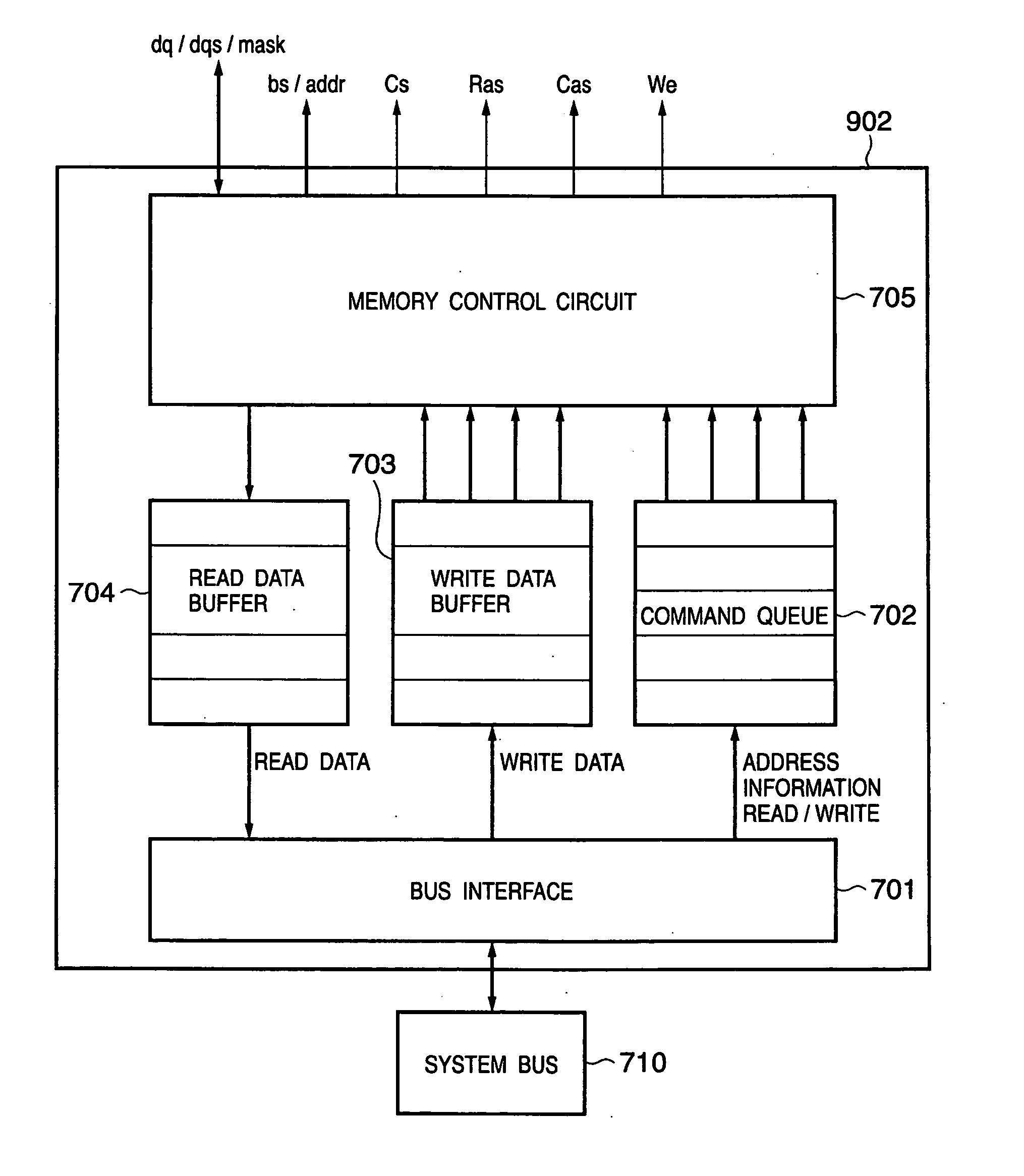
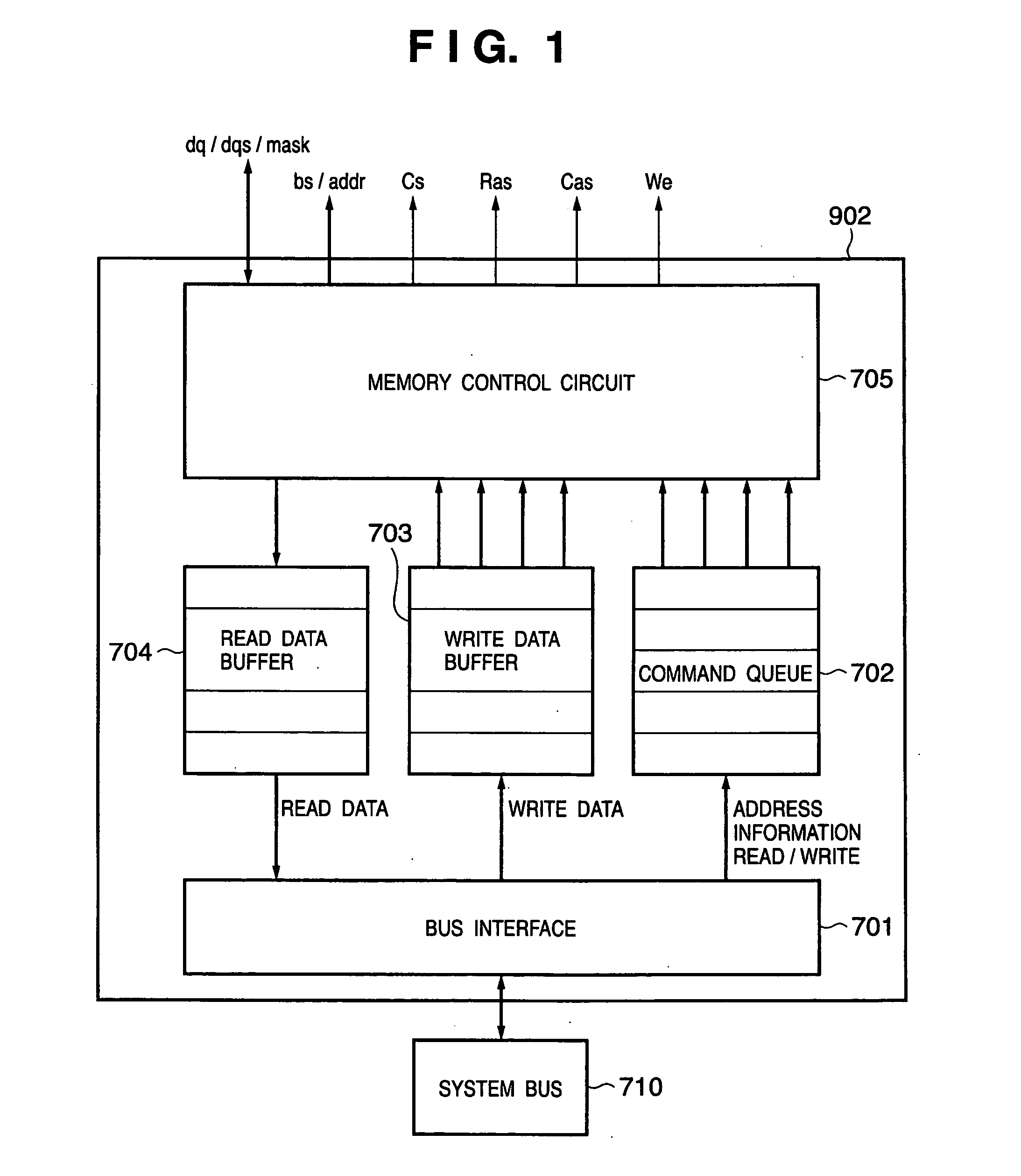
[0136] the present invention will be described next. The block diagram of this embodiment, the view for explaining the configuration of a system LSI 800, and details of a memory controller are the same as in FIGS. 8, 9, and 1.

[0137]FIGS. 12 and 13 are views for explaining the bus protocol of a system bus 920 according to the second embodiment of the present invention. FIG. 12 shows read transfer, and FIG. 13 shows write transfer. As described above, the system bus 920 has a multi-layered architecture so that a bus master can be regarded as if it were connected to an arbitrary bus slave in a one-to-one correspondence.

[0138] The signals included in the system bus 920 will be described below. A description of signals common to the first embodiment will be omitted. [0139] b_size[3:0] Access Size Master→Slave

[0140] Burst size (b_size[3:0]) (Master→Slave) indicates the number of bursts of bus transfer on the system bus 920, for which 1 to 16 beats can be designated. Burst size is define...


PUM


Abstract

A flower arrangement that appears to be a cake. A piece of foam, shaped in the shape of a cake, having flowers inserted into the foam, and then placed on a cake plate or platter, and then placed in a cake box.

Description

BACKGROUND OF THE INVENTION [0001] 1. Field of the Invention [0002] The present invention relates to a memory control apparatus and method. [0003] 2. Description of the Related Art [0004] As the semiconductor and microprocessor technologies progress, the field of application of embedded systems is steadily expanding. Most popular electronic and electric devices use embedded systems. Additionally, along with the recent increase in integration of LSIs, a so-called system LSI is becoming common which integrates the controller function of an embedded device in one LSI. [0005]FIG. 7 is a view showing a configuration that implements an embedded system of OA equipments by using a system LSI disclosed in, e.g., U.S. Pat. No. 6,480,916. [0006] Referring to FIG. 7, a system LSI 100, memory 101, and various kinds of IO interfaces are mounted on an embedded system board 110. The system LSI 100 is a single-chip scanning printing engine. More specifically, the system LSI 100 incorporates a proces...

Claims


Application Information

Patent Timeline
IPC IPC(8): G06F3/00G06F13/00
CPCG06F13/1626
Inventor MINAMI, TOSHIAKI
Owner CANON KK
Why Eureka
Try Eureka