Combined Cycle Power Plant

a combined cycle and power plant technology, applied in the direction of hot gas positive displacement engine plants, machines/engines, jet propulsion plants, etc., can solve problems such as unavoidable performance reduction

Inactive Publication Date: 2007-01-25
GENERAL ELECTRIC CO
View PDF16 Cites 64 Cited by
  • Summary
  • Abstract
  • Description
  • Claims
  • Application Information

AI Technical Summary

Benefits of technology

[0009] The present application further describes a combined cycle power plant. The power plant may include a gas turbine, a steam turbine, a heat recovery steam generator, a feedwater heater positioned down stream of the steam turbine, and a fuel moisturization system in communication with...

Problems solved by technology

This minimum HRSG exit gas temperature constraint results in an unavoidable perf...

Method used


Image

  • Combined Cycle Power Plant
  • Combined Cycle Power Plant
  • Combined Cycle Power Plant

Examples


Embodiment Construction

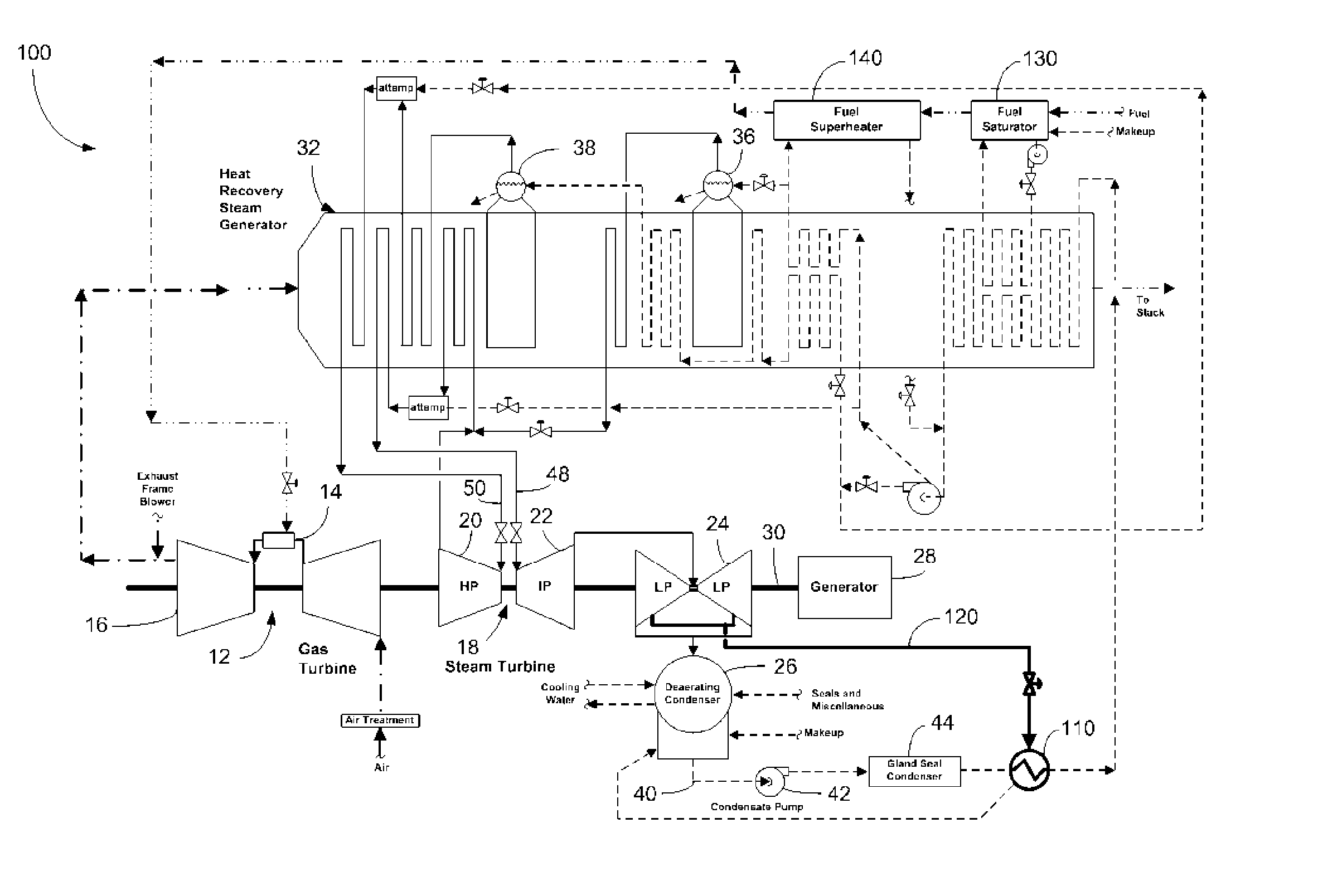
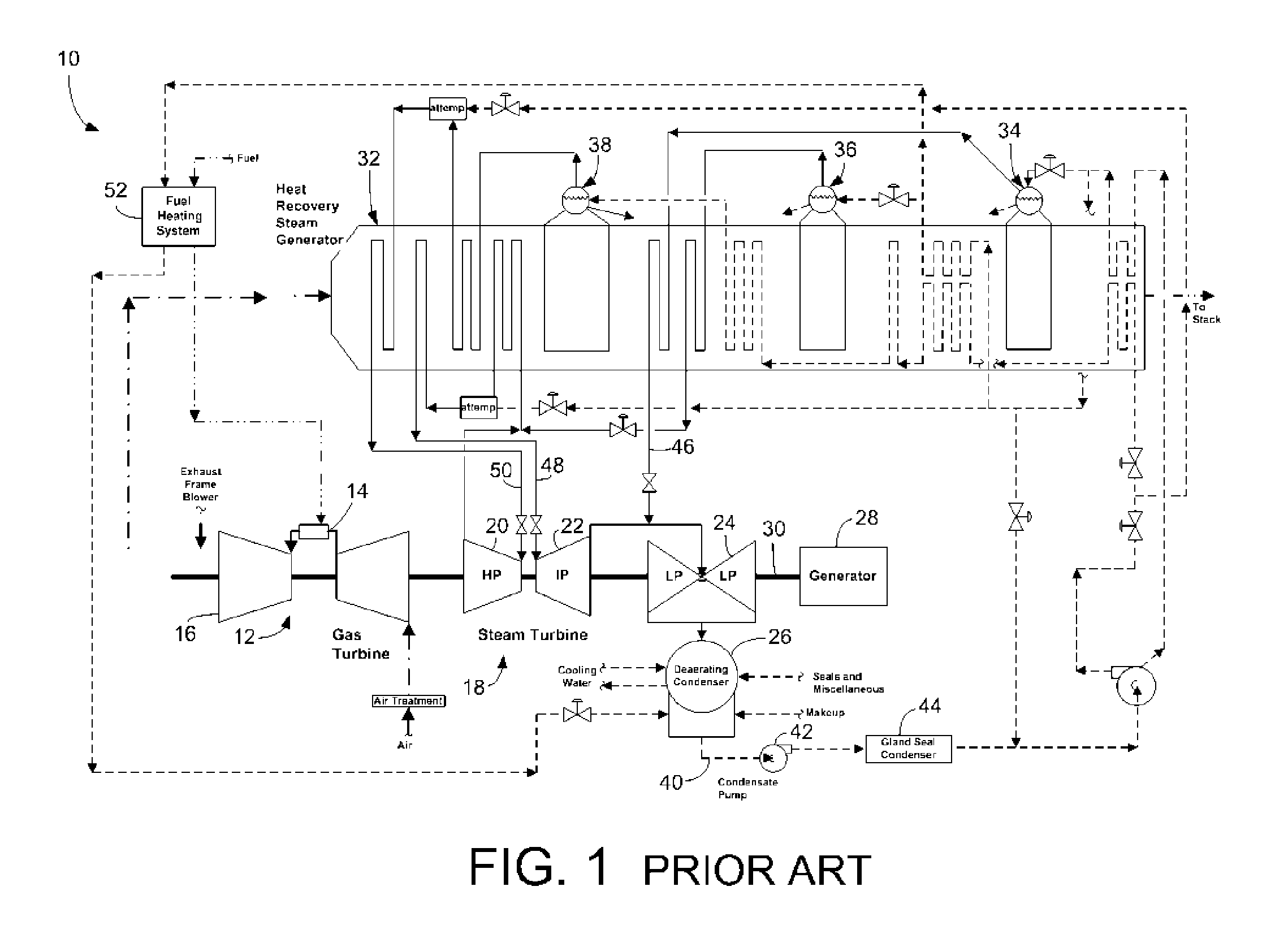
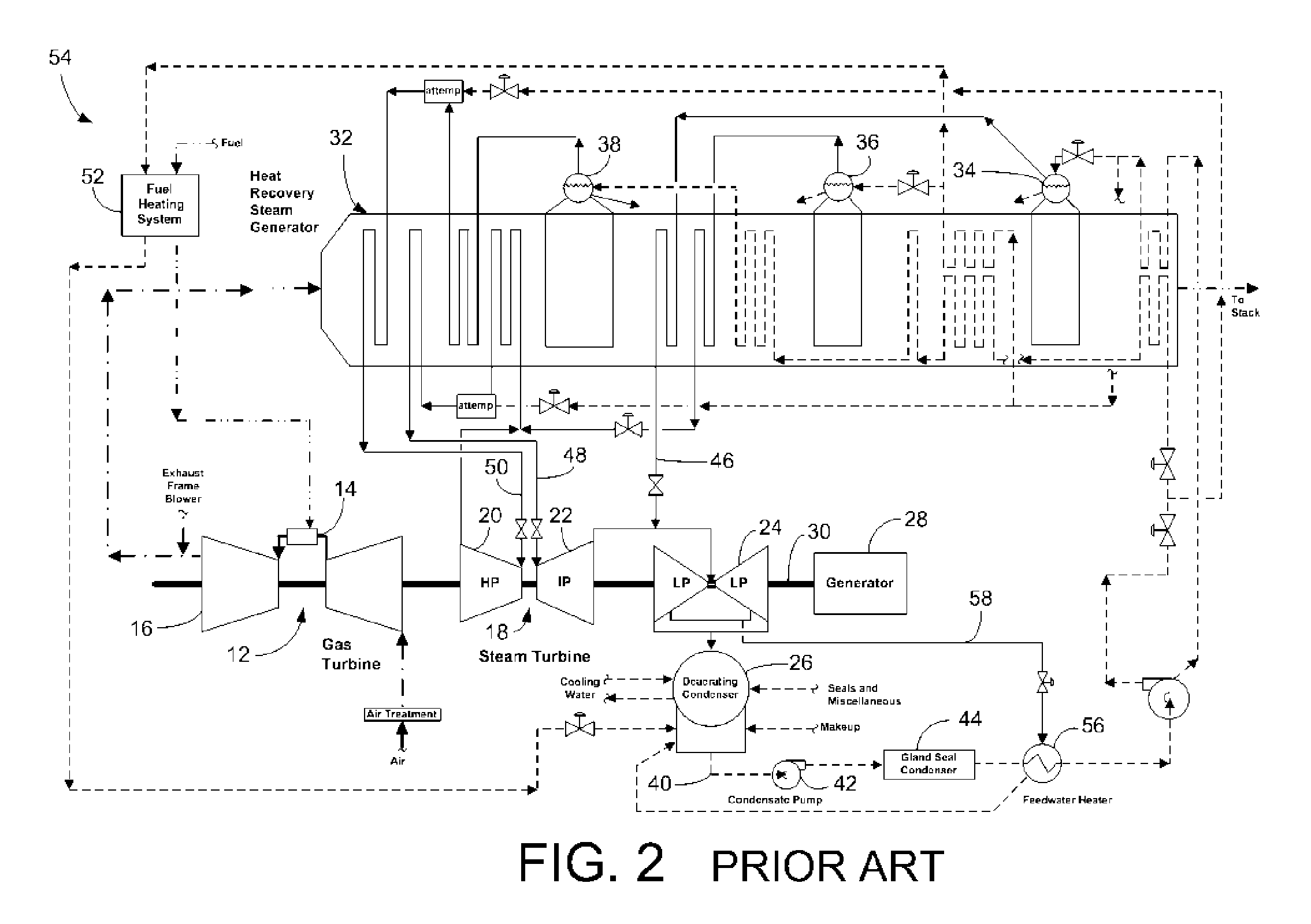
[0019] Referring now to the drawings, in which like numerals indicate like elements throughout the several views, FIG. 1 shows a known combined cycle power plant 10 with no stack temperature limit constraint. The power plant 10 includes a gas turbine system 12 with a combustion system 14 and a turbine 16. The power plant 10 further includes a steam turbine system 18. The steam turbine system 18 includes a high pressure section 20, an intermediate pressure section 22, and one or more low pressure sections 24 with multiple steam admission points at the different pressures. The low pressure section 24 exhausts into a condenser 26. The steam turbine system 18 drives a generator 28 that produces electrical power. The gas turbine 12, the steam turbine system 18, and the generator 28 may be arranged on a single shaft 30. Other configurations may be used.

[0020] The steam turbine system 18 is associated with a multi-pressure HRSG 32. The HRSG 32 is a counter flow heat exchanger such that as...


PUM


Abstract

A combined cycle power plant including a gas turbine, a steam turbine, and a heat recovery steam generator. The power plant also includes a feedwater heater positioned downstream of the steam turbine and a fuel moisturization system in communication with the heat recovery steam generator.

Description

TECHNICAL FIELD [0001] The present invention relates generally to a gas fired combined cycle power plant and more particularly relates to a modified bottoming cycle for improved output and efficiency. BACKGROUND OF THE INVENTION [0002] A combined cycle power plant utilizes a gas turbine and a steam turbine in combination to produce power. The power plant is arranged such that the gas turbine is thermally connected to the steam turbine through a heat recovery steam generator (“HRSG”). The HRSG is a non-contact heat exchanger that allows feedwater for the steam generation process to be heated by otherwise wasted gas turbine exhaust gases. The HRSG is a large duct with tube bundles interposed therein such that water is heated to steam as the exhaust gases pass through the duct. The primary efficiency of the combined cycle arrangement is the utilization of the otherwise wasted gas turbine exhaust gases. [0003] Modern combined cycles typically employ two (2) or three (3) steam generation...

Claims


Application Information

Patent Timeline
IPC IPC(8): F02C6/18F02C3/30
CPCF01K21/047Y02E20/16F02C6/18
Inventor SMITH, RAUB W.RANASINGHE, JATILAGULEN, CAN
Owner GENERAL ELECTRIC CO
Why Eureka
Try Eureka