Abutment module

a technology of abutment module and abutment body, which is applied in the direction of large fixed members, measurement/indication equipment, precision positioning equipment, etc., can solve the problem of low energy requirement in comparison with conventional electrically operated abutment module, and achieve the effect of more economic application

Active Publication Date: 2007-01-25
UNTERHUBER SEBASTIAN
View PDF3 Cites 4 Cited by
  • Summary
  • Abstract
  • Description
  • Claims
  • Application Information

AI Technical Summary

Benefits of technology

[0004] One object of the invention is to provide an abutment module of the type initially mentioned which as compared with conventional electrically operated abutment modules is more universal and more economic in application.

Problems solved by technology

Furthermore the energy requirement is low in comparison with conventional electrically operated abutment modules.

Method used


Image

  • Abutment module
  • Abutment module
  • Abutment module

Examples


Embodiment Construction

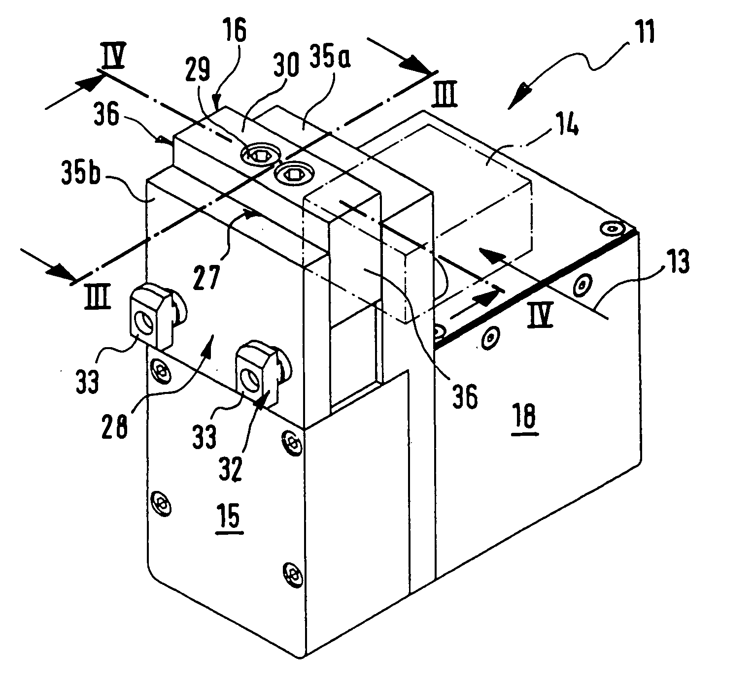
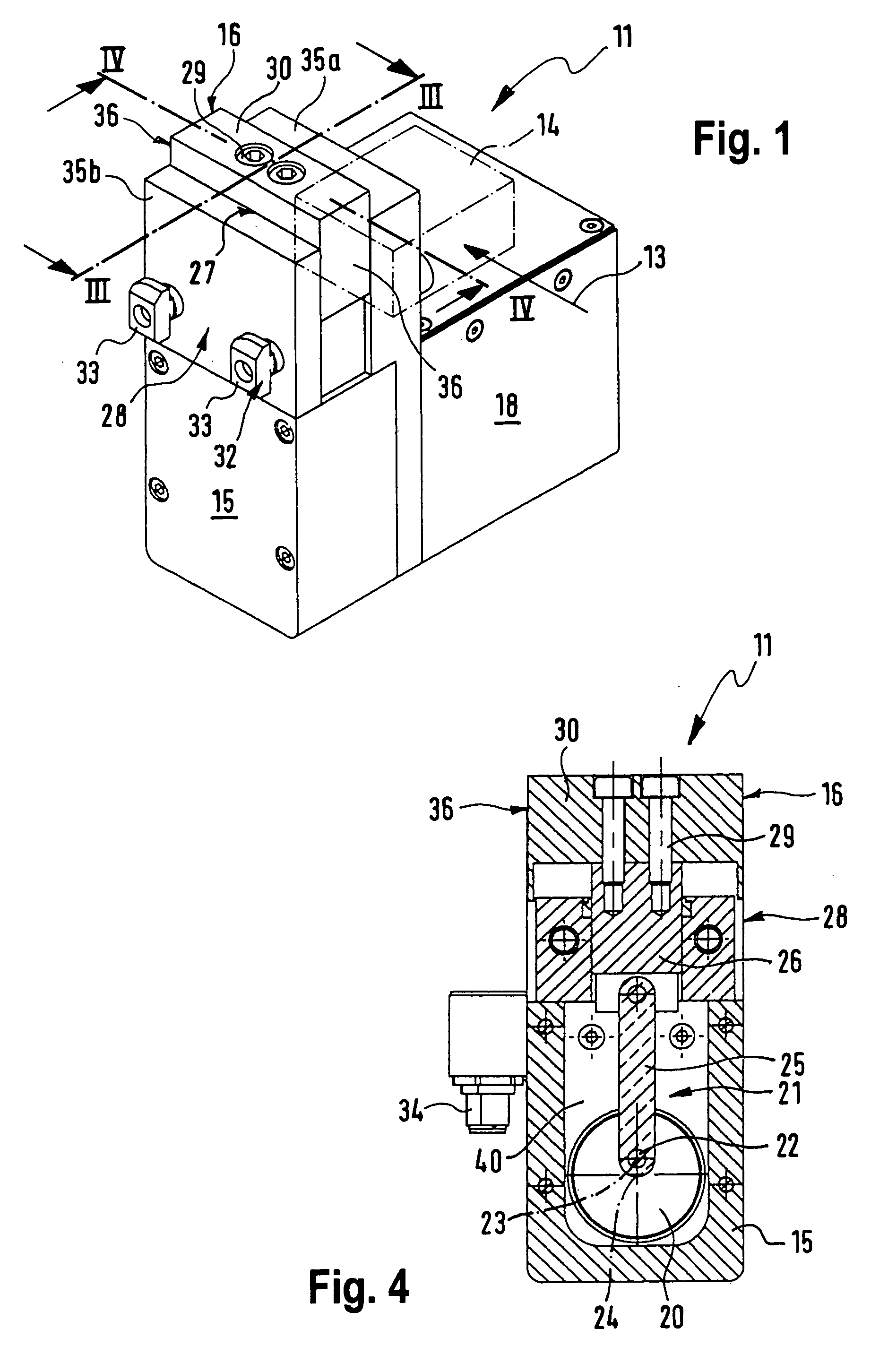
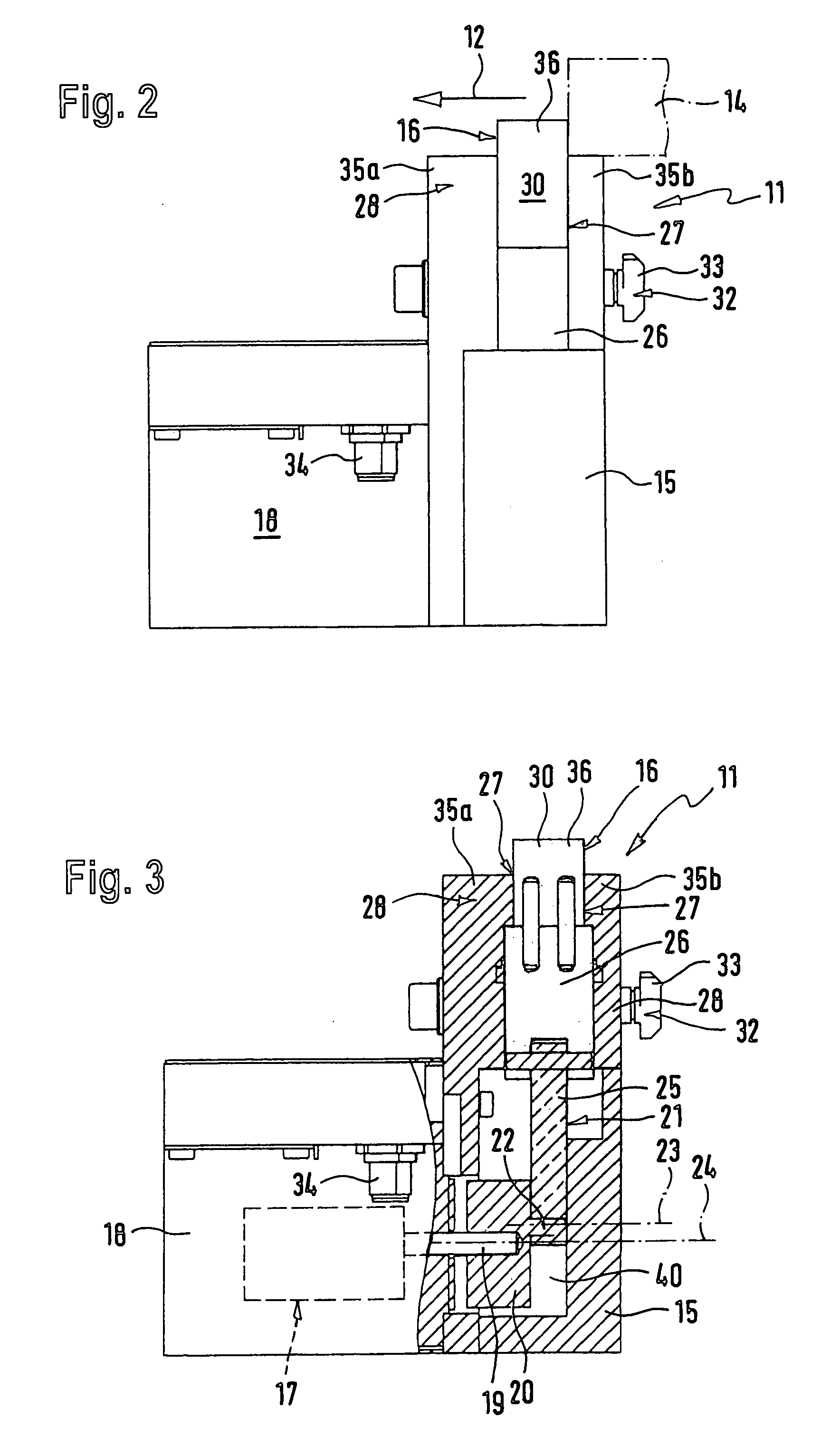
[0024]FIGS. 1 through 4 show a first working embodiment of the abutment module 11 in accordance with the invention, which preferably is employed in automatic processing and conveying equipment in order to singularize objects 14, for example workpieces or the like, moving in a plane of motion in a first direction of working motion 12 (FIG. 2) or in a second direction 13 of working motion (FIG. 1) extending essentially perpendicularly to the first direction 12 of working motion. After singularizing the objects same may be individually treated, diverted or the like.

[0025] The abutment module 11 possesses a base 15 on which an abutment member 16 is arranged which by means of an electrical rotary drive 17 is able to be shifted out of the plane of motion of the objects 14 and back into it.

[0026] The electrical rotary drive 17 is according to a first embodiment of the invention in the form of an electrical servo-motor and is located in a drive module unit 18 separate from the base 15 and...


PUM

PropertyMeasurementUnit
axis of rotationaaaaaaaaaa
forceaaaaaaaaaa
resilient return forceaaaaaaaaaa

Abstract

A abutment module, more particularly for automatic processing and conveying equipment, comprises an abutment member arranged on a base for objects moving in a movement plane in a current direction of working motion, such abutment member being able to be moved out of and back into such plane of movement it by an electrical actuating means, and an electrical rotary drive is provided for the electrical operation.

Description

BACKGROUND OF THE INVENTION [0001] The invention relates to an abutment module more particularly for automatic processing and conveying equipment, comprising an abutment member arranged on a base for objects moving in a movement plane in a current direction of working motion, such abutment member being able to be moved out of such plane of movement and into it by an electrical operation. THE PRIOR ART [0002] Fluid power operated abutment modules are known, see for example the European patent publication 0 484 648. The abutment described therein is able to be shifted by the intermediary of a pneumatically operated setting piston out of the plane of motion of approaching workpieces and back into it. For compressed air operation a compressed air connection is provided for the regulated compressed air to be supplied by. Furthermore a damping means is provided for the abutment so that the movement of the abutting workpieces may be damped. [0003] In certain processing and conveying equipm...

Claims


Application Information

Patent Timeline
Patent Type & Authority Applications(United States)
IPC IPC(8): B23K26/02
CPCB65G47/8815B23Q5/268B23Q5/28B23Q5/40B23Q16/005B23Q17/22B23Q2705/14B23Q2716/08B25B11/00
Inventor UNTERHUBER, SEBASTIANWORNER, HELMUT
Owner UNTERHUBER SEBASTIAN
Why Eureka
Try Eureka