Electrically controlled tiltable microstructures

a microstructure and tilting technology, applied in the field of microstructures, can solve the problems of difficult to achieve a flat mirror surface, temperature and material limitations, and difficult to achieve both qualities in micromachined devices, and achieve the effect of large tilting angle and large fill factor

Inactive Publication Date: 2007-01-25
TELEDYNE LICENSING
View PDF6 Cites 9 Cited by
  • Summary
  • Abstract
  • Description
  • Claims
  • Application Information

AI Technical Summary

Benefits of technology

[0008] The present invention provides an electrically controlled microstructure that can be capable of relatively large angle tilts, with a smooth and sturdy surface for mirror or other applications, a capacity for a large fill factor, and applications for tilting, tilting and tipping (tilting about two different axes), and tilting combined with a piston motion.

Problems solved by technology

Achieving both qualities in micromachined devices has proven to be very difficult.
The mirrors are co-fabricated with the circuitry, leading to temperature and material limitations such as difficulty in achieving a flat mirror surface, especially when coatings have applied to it, scaling the mirrors in size, optical power and reflectivity limitations, and the proximity of the mirrors to the supporting substrate surface which limits their tilt angle.
However, all connections are made along the side of the device, which limits its scalability to large scale 2-dimensional arrays, and it has a low fill factor (percentage of total array area occupied by mirror surfaces).
While the mirrors can be used to point a beam among different reception optical fibers, the relatively large spacing between mirrors makes the array unusable for quality display purposes.

Method used


Image

  • Electrically controlled tiltable microstructures
  • Electrically controlled tiltable microstructures
  • Electrically controlled tiltable microstructures

Examples


Embodiment Construction

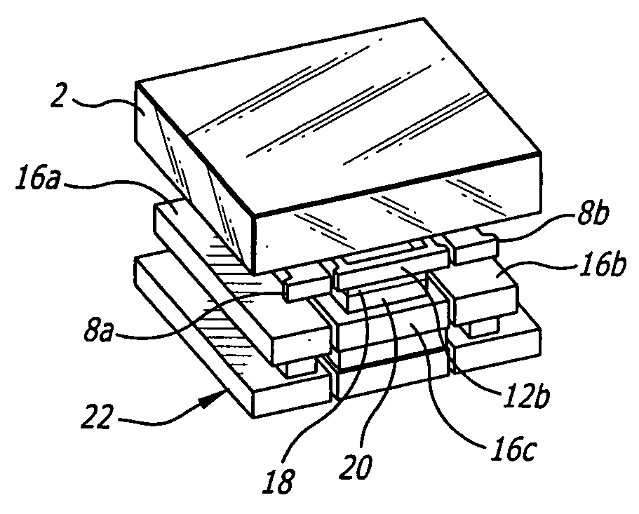
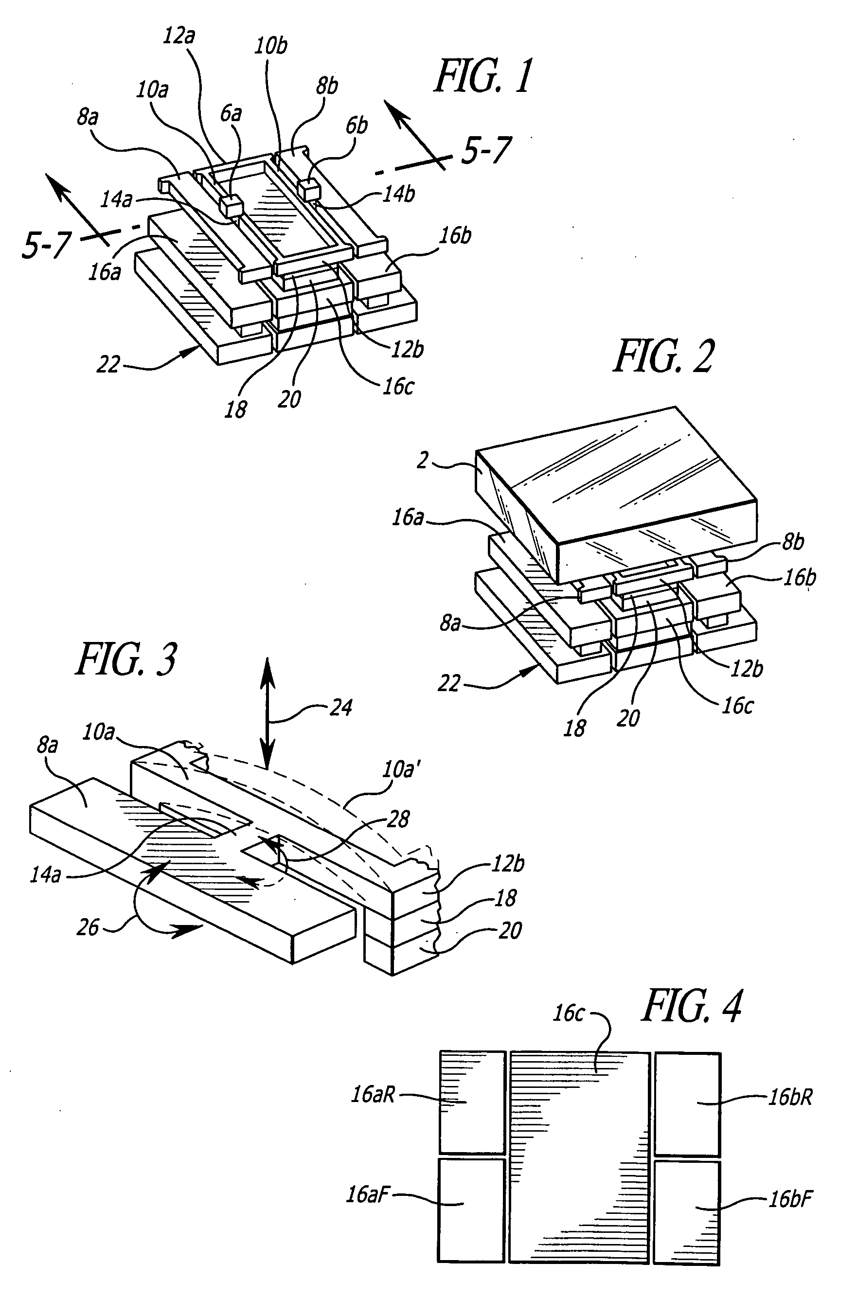
[0024] An illustrative microstructure device which supports a tiltable platform in accordance with the invention is illustrated in FIGS. 1 and 2. As used herein, the term “platform” includes a mirror but is not limited to mirror applications; it can also provide a base for other functions such as filters, gratings, and non-optical applications.

[0025] Although not required by the invention, the fabrication preferably employs a hybrid micromachining approach that combines bulk and surface micromachine techniques. This approach to forming a microstructure is disclosed in U.S. Pat. No. 6,587,613 by the present inventor, issued Jul. 1, 2003, the contents of which are incorporated by reference herein. It involves the formation of a support structure for a bulk micromachined element by fabricating the support structure on the element using surface micromachining techniques. One implementation uses a 5-level surface micromachining technology that allows for the fabrication of complex movab...


PUM


Abstract

A support structure extends upwards from a substrate and supports a tiltable platform, the upper surface of which can be a mirror, by means of spaced flexible couplings that enable the platform to tilt relative to the support structure. Respective electrodes associated with the substrate and platform control the platform tilt in response to applied signals. The platform electrodes are preferably spaced below and tilt with the platform, with the platform extending laterally from the support structure further than the platform electrodes. The platform is preferably bulk micromachined, and the support structure surface micromachined.

Description

BACKGROUND OF THE INVENTION [0001] 1. Field of the Invention [0002] This invention relates to electrically controlled microstructures with tiltable platforms, and has particular application to micromirrors. [0003] 2. Description of the Related Art [0004] There are various applications for micromirror arrays with tilting capabilities, such as optical cross-couplers, projection displays, optical attenuators and laser beam scanning and pointing systems. It is desirable that the micromirrors have a large tilt angle, to maximize the contrast between “on” and “off” states, and good mirror surface quality to reduce non-specular scatter that degrades image contrast. Achieving both qualities in micromachined devices has proven to be very difficult. [0005] In one approach, micromirrors formed from thin metal films that are monolithically integrated onto the control circuitry have been used for projector displays. The mirrors are co-fabricated with the circuitry, leading to temperature and mat...

Claims


Application Information

Patent Timeline
Patent Type & Authority Applications(United States)
IPC IPC(8): A47F5/00
CPCB81B3/0062B81B2201/033G02B26/0841B81B2203/053B81B2203/058B81B2201/042
Inventor DENATALE, JEFFREY F.LI, XIAOBIN
Owner TELEDYNE LICENSING
Why Eureka
Try Eureka