
Battery detection interface

a technology of battery element and detection interface, which is applied in the field of battery element detection interface, can solve the problems of significant risk, serious safety risk of electronic devices when used with copied battery elements, and only temporary advantages,

Inactive Publication Date: 2007-01-25
NOKIA CORP
View PDF11 Cites 32 Cited by
  • Summary
  • Abstract
  • Description
  • Claims
  • Application Information

AI Technical Summary

Benefits of technology

[0013] It is an objective of the present invention to provide an interface arrangement and a method for reliable battery identification and for removal detection, the invention allowing the drawbacks associated with the prior art to be eliminated or reduced.
[0022] transfer of both analogue data and digital data does not increase the number of electrical coupling elements between a battery element and an electronic device.

Problems solved by technology

The advantage reached by this method is, however, only temporary because a third party battery manufacturer may copy the mechanical shape of a battery element.
If a third party battery maker does not copy the technology inside a battery element, a copied battery element causes a serious safety risk when used with the electronic device.
A drawback of distinguishing new-technology battery elements from older-generation battery elements based on the measured voltage Um is the fact that for third parties it is very straightforward to produce battery elements whose BSI resistors are similar to those of new-technology battery elements but a battery cell unit represent older-generation technology.
In other words, there is a significant risk that on the market there will be such counterfeit battery elements that from the viewpoint of the distinguishing method resemble new-technology battery elements but that actually are older-generation battery elements.
This kind of counterfeit battery element causes a serious safety risk when used with an electronic device.
Firstly, when third party battery makers notice their business is going to end, they are focusing to break the encrypting of the authentication algorithm.
Secondly, allowing only battery elements manufactured by a device vendor may be even commercially unattractive.

Method used


Image

  • Battery detection interface
  • Battery detection interface
  • Battery detection interface

Examples


Embodiment Construction

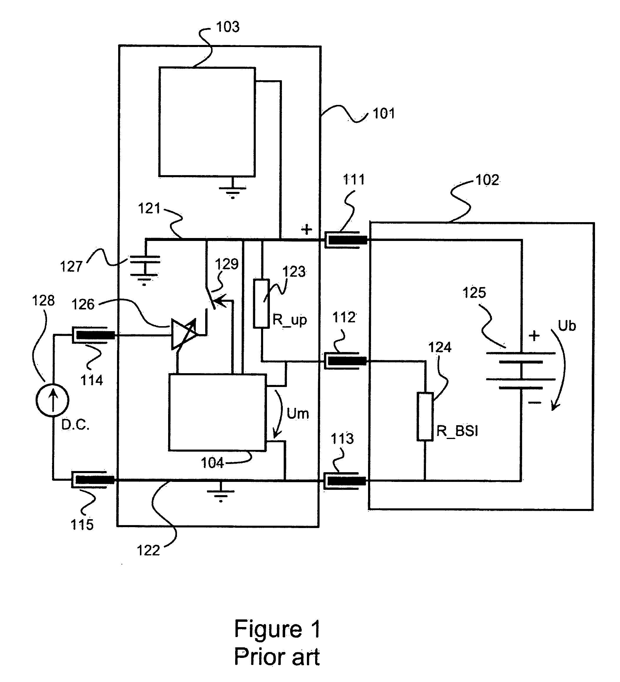
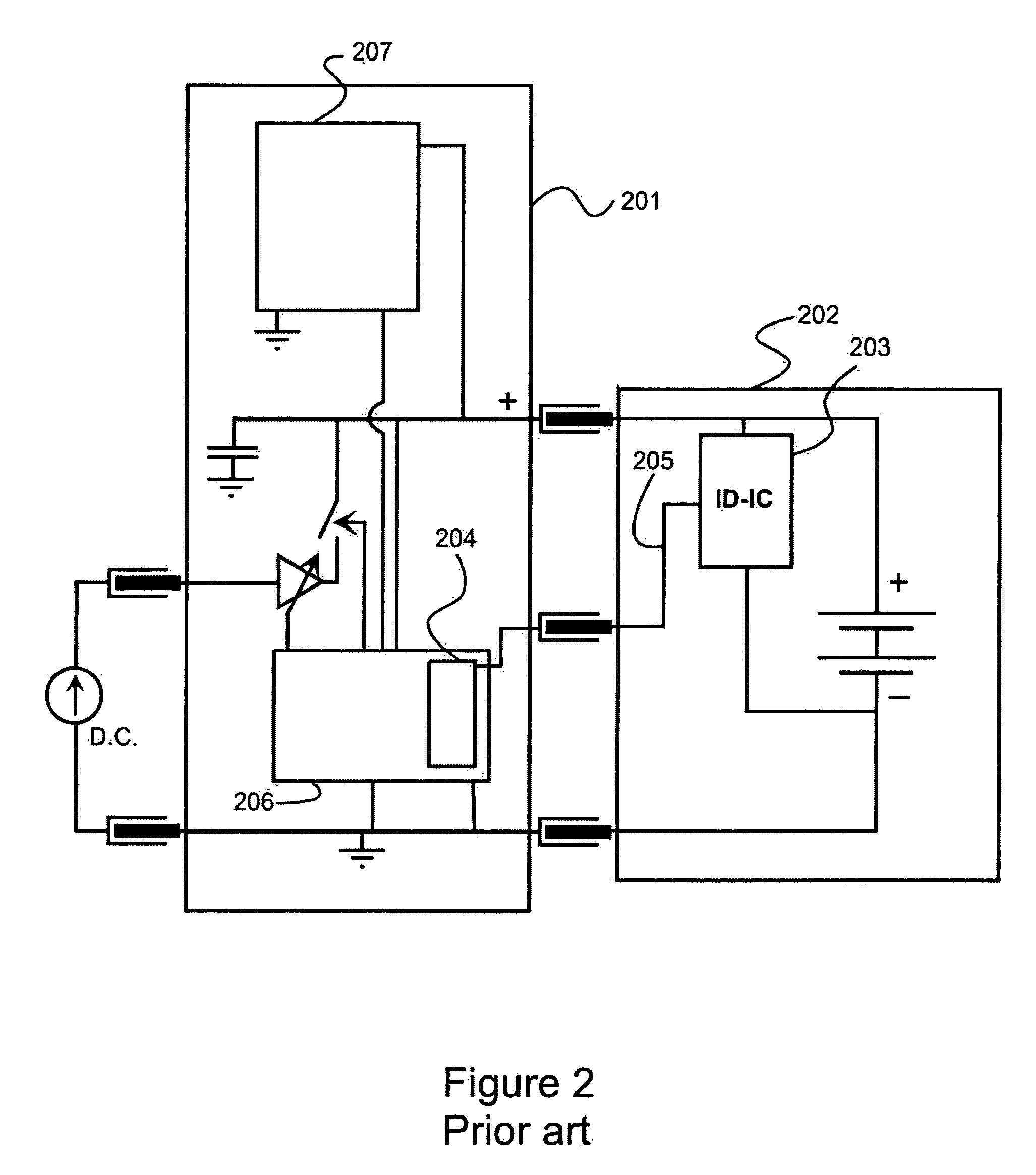
[0057]FIGS. 1-2 have been explained above in the description of the prior art.

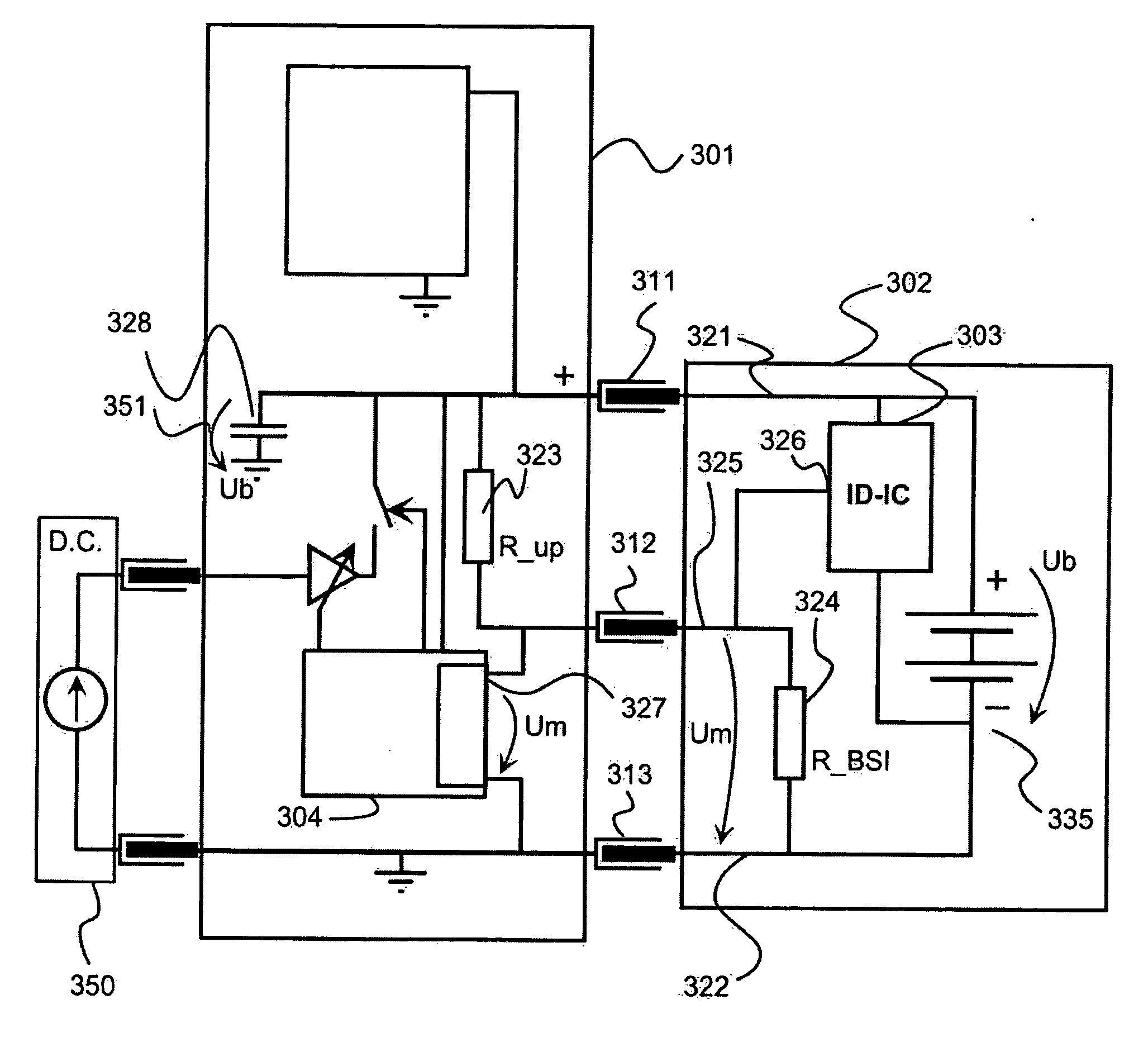
[0058]FIG. 3 shows a combined analogue and digital interface between a battery element and an electronic device according to a preferred embodiment of the invention. A battery element 302 comprises an identification circuit 303 (ID-IC) and a BSI-resistor 324. Resistance of a BSI-resistor represents analogue data associated with the battery element. The identification circuit 303 comprises a storage unit for digital data and a logic unit needed in transfer of the digital data to an electronic device 301. The electronic device comprises a control element 304 and a pull up resistor 323. The electrical device 301 and the battery element 302 are coupled with each other via electrical coupling elements 311, 312, and 313. The control element 304 comprises a measuring unit for measuring voltage Um over the BSI resistor 324 and a logic unit needed in transfer of digital data from the identification circuit 303. Th...


PUM


Abstract

It is an objective of the present invention to provide an interface arrangement between a battery element (302) and an electronic device (301), e.g. a mobile phone, for reliable battery identification and for removal detection. The objectives of the invention are achieved with a combined analogue and digital interface between a battery element (302) and an electronic device (301) so that both analogue and digital data can be transferred from a battery element to an electrical device. Reliable digital authentication is used for determining if a battery element connected to an electronic device represents new battery technology. An analogue signalling scheme is used for identifying different battery elements representing older-generation battery technologies and for detecting battery removals. Digital data read from the battery element (302) may contain, for example, information for charging control, a discharge curve, and a serial number of the battery element.

Description

FIELD OF THE INVENTION [0001] The invention relates to a method and arrangement for changing information between a battery element and a battery-powered electronic device. Especially the invention concerns an electrical interface between a battery element and an electronic device such that information related to a battery element can be transferred to an electronic device. BACKGROUND OF THE INVENTION [0002] The widespread use of battery-powered electronic devices (e.g. cellular mobile phones, laptops, palmtops) with high performance relies on efficient battery utilization. These kinds of devices typically use re-chargeable batteries like lithium-ion, nickel-cadmium or nickel metal hydride batteries. New battery technology gives longer working time to battery-powered devices through providing a wider voltage range. A new-technology battery can be charged up to a higher voltage and / or it can be discharged down to a lower voltage than a corresponding older generation battery. Many time...

Claims


Application Information

Patent Timeline
IPC IPC(8): H02J7/00
CPCG01R31/043H01M10/48H01M10/46H01M10/44G01R31/68Y02E60/10
Inventor ANTTILA, JEREAALTONEN, MARKUSHURULA, MIKA
Owner NOKIA CORP
Features
  • Generate Ideas
  • Intellectual Property
  • Life Sciences
  • Materials
  • Tech Scout
  • Unparalleled Data Quality
  • Higher Quality Content
  • 60% Fewer Hallucinations
Learn More