Antenna for detecting magnetic field, and gate for detecting detection tag employing the antenna

Inactive Publication Date: 2007-01-25
LINTEC CORP +1
View PDF6 Cites 8 Cited by
  • Summary
  • Abstract
  • Description
  • Claims
  • Application Information

AI Technical Summary

Benefits of technology

[0021] In the antenna for detecting a magnetic field according to the present invention, a plurality of loop antennas (which are small as compared with conventional 8-shaped antenna) are arranged in a state dispersed in a large area and are connected to each other; therefore, a magnetic field can be detected in a large area. In this case, each two adjacent loop antennas are reversed in the direction in which the electric wire constituting each loop antenna is wound. With this way of winding, the magnetic flux directions of two adjacent loop antennas are reversed, which cancels the external noise generated and consequently heightens the ratio of detection of target signal, resulting in a high S / N ratio.
[0023] In contrast, the present invention antenna is constituted by relatively small loop antennas; therefore, the noise generated can be cancelled and signal cancellation can be prevented by arranging individual loop antennas apart from each other. In other words, it is easy to control a balance between the adverse effect of noise and the reception of signal. Reduction in the voltage (noise) induced by the coil for magnetic field generation is possible even with the 8-shaped antenna and there is a certain effect in the center of the antenna. When a plurality of small loop antennas are arranged as in the present invention, it is possible to arrange them apart from each other and accordingly there can be obtained a S / N ratio higher than in the 8-shaped antenna.

Problems solved by technology

Consequently, there is a problem that the signal of small detection tag may not be detected.

Method used


Image

  • Antenna for detecting magnetic field, and gate for detecting detection tag employing the antenna
  • Antenna for detecting magnetic field, and gate for detecting detection tag employing the antenna
  • Antenna for detecting magnetic field, and gate for detecting detection tag employing the antenna

Examples


example 1

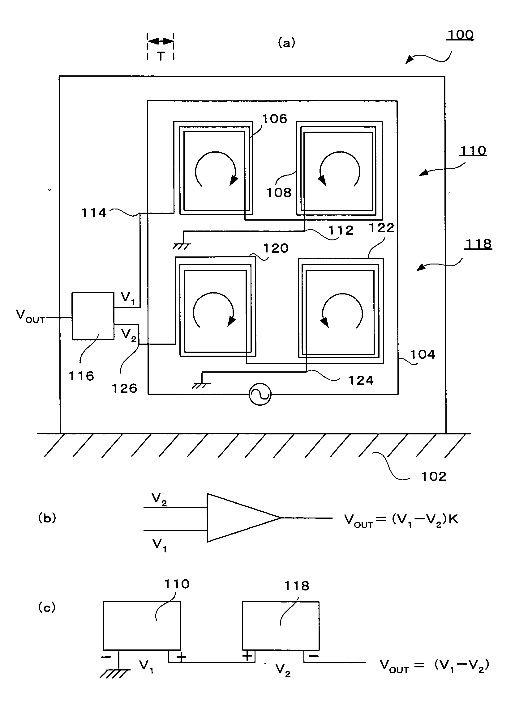
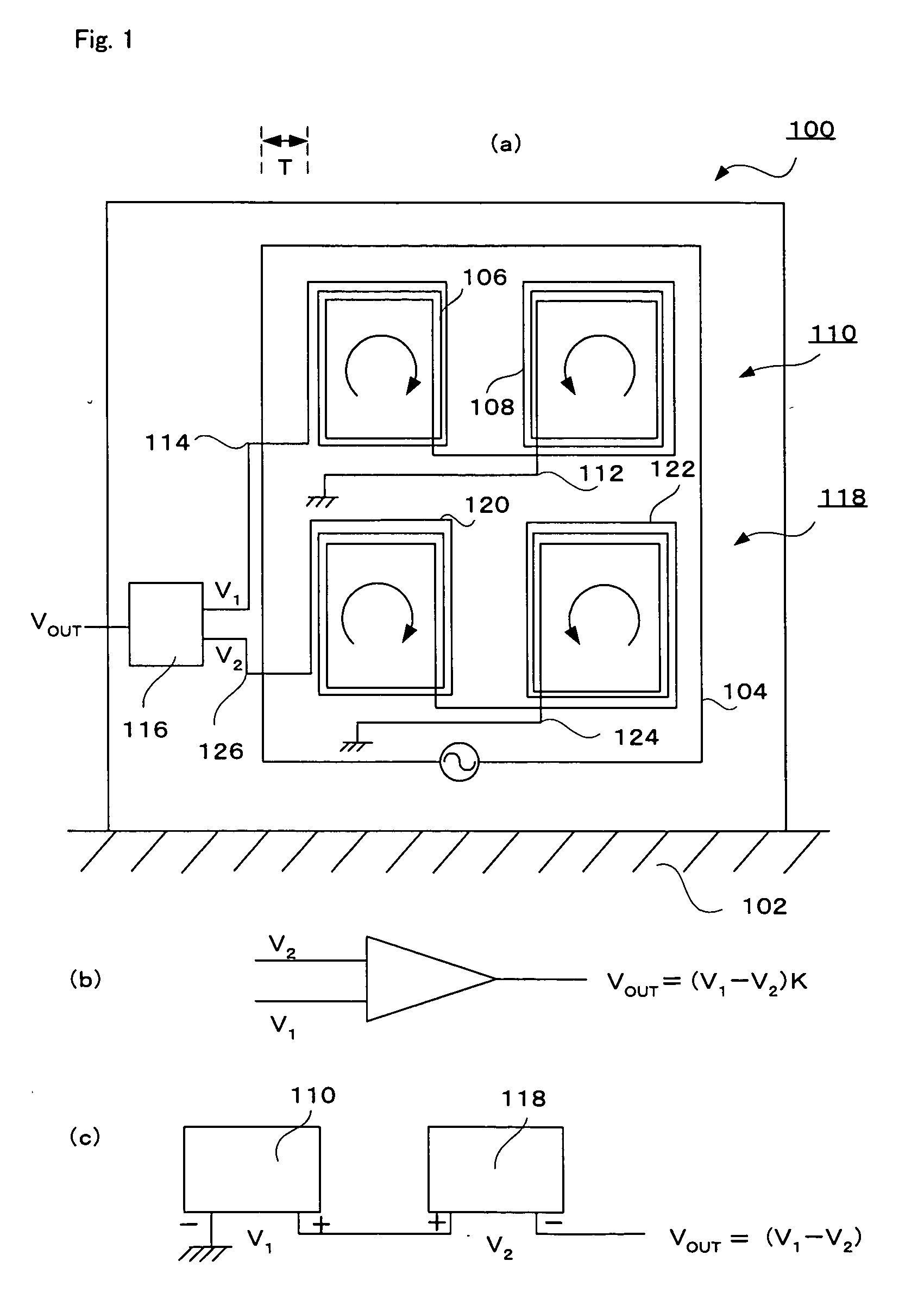
[0042] A gate shown in FIG. 1 was produced. An electric wire was wound in a loop shape of 120 cm in length and 60 cm in width to form a coil 104 for magnetic field generation. The number of turns of the coil 104 for magnetic field generation was 100. In the upper half of the loop plane formed by the coil 104 for magnetic field generation, two loop antennas 106 and 108 wound in opposite directions were connected in series. Each loop antenna was 40 cm in length and 10 cm in width and its number of turns was 80. The distance between the two loop antennas 106 and 108 was 14 cm, and the distance T between the coil 104 for magnetic field generation and the loop antenna 106 or 108 was 23 cm.

[0043] Loop antennas 120 and 122 having the same constitution as the loop antennas 106 and 108 were fitted below the loop antennas 106 and 108. The distance between the two loop antennas 120 and 122 and the distance between the coil 104 for magnetic field generation and the loop antenna 120 or 122 were...


PUM


Abstract

The present invention discloses: an antenna for detecting a magnetic field, wherein a plurality of loop antennas wound in opposite directions are connected in series and placed in a plane, a magnetic field detector comprising a plurality of the above antennas for detecting a magnetic field and an output circuit for taking out a differential output between the outputs of the plurality of antennas, and a gate for detecting detection tag comprising the above magnetic field detector and a coil for magnetic field generation.

Description

TECHNICAL FIELD [0001] The present invention relates to an antenna for detecting a magnetic field which detects a detection tag or the like by detecting a change in magnetic field, a magnetic field detector employing the antenna, and a gate for detecting detection tag. More particularly, the present invention relates to an antenna for detecting a magnetic field which is constituted by a plurality of loop antennas and gives a high signal / noise ratio (S / N ratio), a magnetic field detector employing the antenna, and a gate for detecting detection tag. BACKGROUND ART [0002] Detection tags employing a magnetic field as a detection means are known. They are adhered to goods, etc., are carried with the goods and, when passing through particular gates, are detected by gates; thereby, the circulation of goods is controlled and the theft of goods is prevented. (Claim 1 of JP 1994-342065A) [0003]FIG. 2 shows an example of conventional detection tag. In FIG. 2, 20 is a soft magnetic substance l...

Claims


Application Information

Patent Timeline
IPC IPC(8): G08B13/24G01S13/74G01V3/10H01Q21/00H04B5/02
CPCG01V3/104H01Q21/06G01R33/02G01V3/10H01Q17/00
Inventor MATSUI, KUNIHIKOHIBARINO, TOSHIHISAMOROYA, TETSUOOISHI, HIROSHI
Owner LINTEC CORP
Why Eureka
Try Eureka