Pulse modulator and pulse modulation method

Active Publication Date: 2007-01-25
NORTHROP GRUMMAN SYST CORP +1
View PDF16 Cites 6 Cited by
  • Summary
  • Abstract
  • Description
  • Claims
  • Application Information

AI Technical Summary

Benefits of technology

[0006] It is therefore an of the invention to provide a pulse modulator and a method for puls

Problems solved by technology

They are, however, expensive and require a relatively large amount of electrical power as well as a number of supply

Method used


Image

  • Pulse modulator and pulse modulation method
  • Pulse modulator and pulse modulation method
  • Pulse modulator and pulse modulation method

Examples


Example

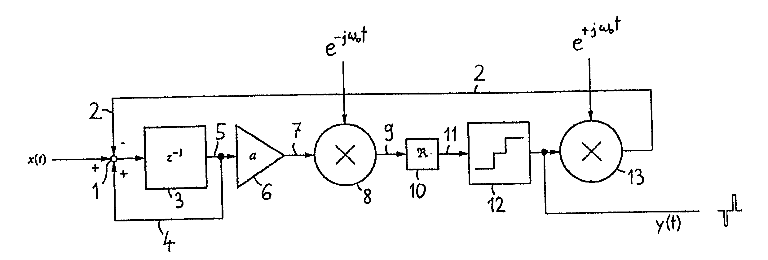
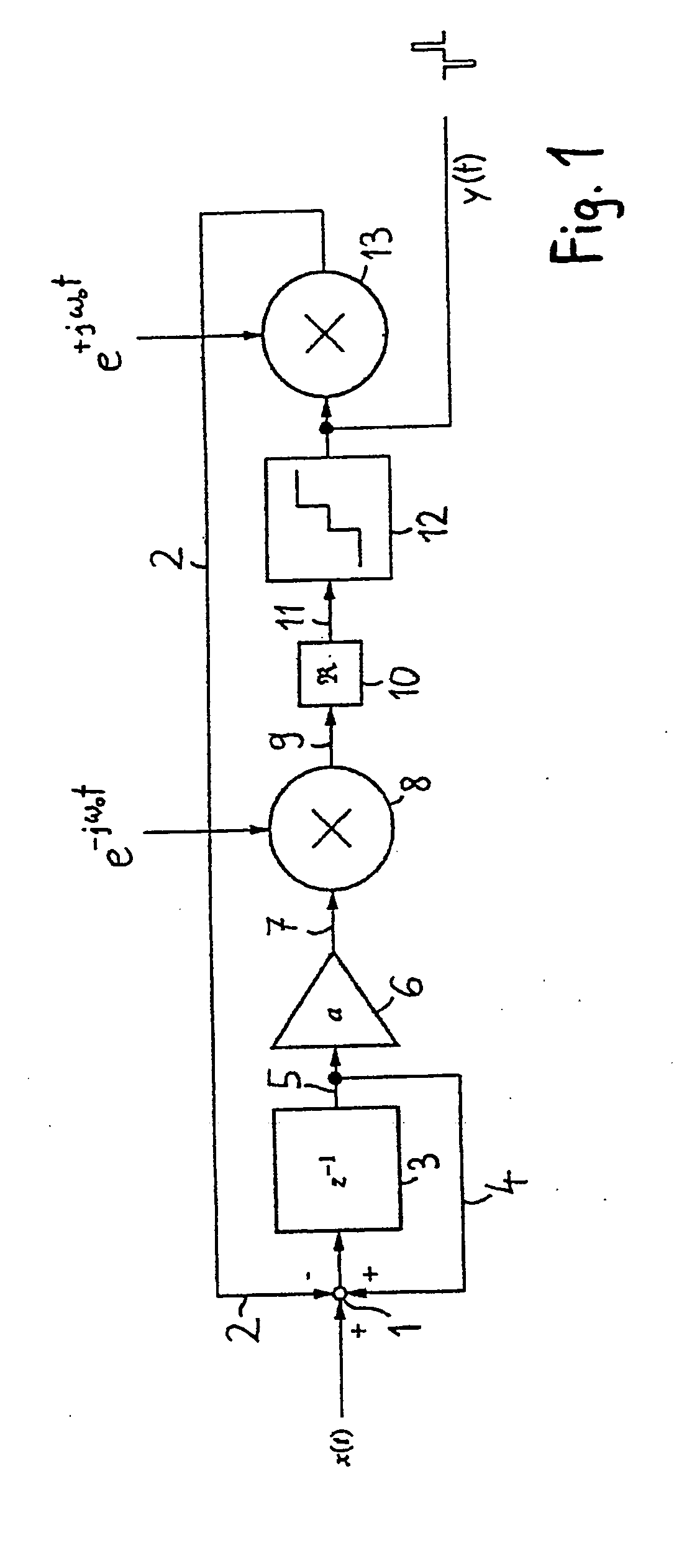
[0021]FIG. 1 is a block diagram of a pulse modulator in accordance with the invention in complex form. A complex input signal x(t) includes real and imaginary parts, each represented as a digital value. A complex feedback signal 2 is subtracted from the complex input signal x(t) in the addition node 1, with their difference representing the control error. The (likewise complex) content of a delay element 3 is added to such difference at the addition node 1. (The content of the delay element 3 is passed via a signal line 4 to the addition node 1.) The delay element 3, combined with the signal line 4, forms a complex integrator stage that integrates the complex control error (i.e. the difference between the input signal and the feedback signal). The integrated signal 5 is amplified by a factor “a” in an amplifier stage 6. An amplified signal 7 is passed to a first multiplication stage 8 where it is multiplied by the complex mixing signal exp(−jω0t) to obtain a signal 9 up-mixed to fre...


PUM


Abstract

A pulse modulator has a subtraction stage that produces a control error signal from the difference between a complex input signal and a feedback signal. A signal conversion stage converts the control error signal to a control signal. The control signal is multiplied by a complex mixing signal at the frequency ω0 in a first multiplication stage. At least one of the real and imaginary parts of the up-mixed control signal is then quantized by a quantization stage to produce a real pulsed signal. The pulsed signal is then employed to produce the feedback signal for the subtraction stage in a feedback unit. The pulse modulator according to the invention allows the range of reduced quantization noise to be shifted toward a desired operating frequency ω0.

Description

BACKGROUND [0001] 1. Field of the Invention [0002] The present invention relates to pulse modulators. More specifically, the invention pertains to a pulse modulator for conversion of a complex input signal to a pulsed signal, and to a method for pulse modulation of a complex input signal. [0003] 2. Description of the Prior Art [0004] Digital / analog converters may be employed to convert digital input signals to analog signals. They are, however, expensive and require a relatively large amount of electrical power as well as a number of supply voltages (frequently). They are also difficult to integrate with digital electronics and, thus, limit miniaturization. [0005] As a result, digital / analog converters are being replaced by digital pulse modulators (e.g., sigma-delta converters) in many applications. A conventional sigma-delta modulator includes an integrator that integrates the difference signal between an input signal and a fed-back quantized signal, as well as a quantizer that qu...

Claims


Application Information

Patent Timeline
IPC IPC(8): H04B14/04H03M7/00
CPCH03M7/3017H03M7/3031H03M7/3026H03K7/00
Inventor SPAHLINGER, GUENTER
Owner NORTHROP GRUMMAN SYST CORP
Why Eureka
Try Eureka