Print blankets for use in electro-statographic printing and methods of using same

Active Publication Date: 2007-01-25
HEWLETT PACKARD DEV CO LP
4 Cites 24 Cited by

AI-Extracted Technical Summary

Problems solved by technology

Since various types of silicone materials are more or less abhesive to the hot toner (which is a hot melt adhesive) and have varying degrees of ruggedness, softness and other required mechanical properties, the choice of a material for transfer layers is a complex task.
A disadvantage of silicone layers, which is directly related to the liquid absorption, is a problem called “image memory”.
This problem is believed to be caused by uneven absorption of carrier liquid over the surface of the blanket.
Another disadvantage of silicone based image transfer layers pertains to their useful lifespan.
Repetitive swelling and drying of the print blanket, and specifically the image transfer layer, often results in the degradation of the mechanical properties of the pr...

Method used

[0029] PIP 104 is optionally discharged and cleaned by a cleaning/discharging unit 112 prior to recharging of PIP 104 in order to start another printing cycle. As substrate 102 passes by ITM 108, the image located on ITM 108 surface 116 is then transferred and affixed to substrate 102. Affixation of the image to substrate 102 is facilitated by locating substrate 102 on the surface 118 of impression roller 114, which applies pressure to substrate 102 by compressing it between impression roller 114 and ITM 108 as the image is being transferred to substrate 102. Eventually, substrate 102 bearing the image exits the printer. In some exemplary embodiments of the invention, the printer is a sheet-fed printer. Optionally, the printer is a web-fed printer.
[0039] In an exemplary embodiment of the invention, image transfer layer 212 is comprised of a fluoroelastomer. Optionally, the fluoroelastomer material is a dipolymer of VF2/HFP. Optionally, the fluoroelastomer material is a terpolymer of VF2/HFP/TFE. Optionally, the fluoroelastomer material is a copolymer of TFE/Propylene and ethylene/TFE/PMVE. Optionally, the fluoroelastomer is a combination of any of the above. Commercially available fluoroelastomer products suitable for use with image transfer layer 212 include the Viton® family of fluoroelastomers by DuPont®, Kalrez®, the Dyneon® family by 3M® and the Technoflon® family by Solvay or FKM. Additives known in the art are optionally added to image transfer layer 212 for properties optimization. For example, carbon black and/or salts are added to optimize the conductivity of the transfer layer by choosing the proper concentration and particle size. Additives like Teflon, silicone and/or others allow optimization of release properties. In some exemplary embodiments of the invention, the elastomer formulation is comprised of no more than 80% fluorine by weight. Optionally, the elastomer formulation is comprised of no more than 71% fluorine by weight. Optionally, the elastomer formulation is comprised of no more than 65% fluorine by weight.
[0042] A blanket 222 is shown in FIG. 2D, wherein compressible layer 208 of other embodiments of the invention is replaced by an additional fluoroelastomer layer 226. Blanket 222 thus is provided with two fluoroelastomer layers, an upper, transfer layer 224 and additional layer 226. In some exemplary embodiments of the invention, additional layer 226 is adapted to provide the same functionality as compressible layer 206 found in other exemplary blanket embodiments. Additional layer 226 is comprised of sufficient thickness to provide reliable and/or high quality transfer of an image to a final substrate. Optionally, additional layer 226 is no more than 200 microns thick. Optionally, additional layer is no more than 500 microns thick. In some exemplary embodiments, additional layer 226 is more than 500 microns thick. In some exemplary embodiments of the invention, manufacturing costs are saved by eliminating the need for an additional component material (spongy compression layer).
[0043] Referring to FIG. 2E, an exemplary blanket 230 is shown wherein a main fluoroelastomer layer 232 is used in lieu of image transfer layer 212, conductive layer 210, under layer 216, and/or compressible layer 208. Main fluoroelastomer layer 232 is adapted to perform a variety of functions, in an exemplary embodiment of the invention. For example, main fluoroelastomer layer 232, it has been shown by the inventors, exhibits sufficient electrical conductivity to act in lieu of conductive layer 210. Optionally, additives such as carbon black and/or salts are included in main fluoroelastomer layer 232 to enhance conductivity of layer 232. Optionally, the portion of the main FE layer further from a surface of main FE layer exhibits enhanced conductivity relative to the portion of main FE layer closer to the surface. Additionally, it has been found by inventors that main fluoroelastomer layer 232 exhibits sufficient micro and macro hardness to provide reliable and/or high quality first (from PIP) and second transfer (to final substrate) of an image. In some exemplary embodiments of the invention, main fluoroelastomer layer 232 is no more than 100 microns thick. Optionally, main fluoroelastomer layer 232 is no more than 500 microns thick. In some exemplary embodiments of the invention, main fluoroelastomer layer 232 is more than 500 microns thick
[0044]FIG. 2F shown an exemplary blanket 240 wherein a hard under layer 242 is provided. In an exemplary embodiment of the invention, hard under layer 242 is provided to enhance application of blanket 240 pressure during image transfers. In an exemplary embodiment of the invention, hard under layer 242 is comprised of Kepton®. In some exemplary embodiments of the invention, hard under layer 242 is no more than 200 microns thick. Optionally, hard under layer 242 is no more than 100 microns thick. In some exemplary embodiments of the invention, hard under layer 242 is between 5-25 microns thick.
[0045] Silicone based image transfer layers, as are known in the art, swell when used in conjunction with a liquid toner. Mineral oils and other liquid components of liquid toner are absorbed by the silicone based image transfer layers. As a result, imag...

Benefits of technology

[0019] An aspect of some exemplary embodiments of the invention relates to providing a print blanket which facilitates manufacture. In an exemplary embodiment of the invention, producing a fluoroelastomer layer as a roll and laminating the layer on top of t...

Abstract

A print blanket for use in electrostatic printing, comprising a body portion; and, an image transfer layer comprising a non-silicone fluoroelastomer.

Application Domain

Technology Topic

Image

  • Print blankets for use in electro-statographic printing and methods of using same
  • Print blankets for use in electro-statographic printing and methods of using same
  • Print blankets for use in electro-statographic printing and methods of using same

Examples

  • Experimental program(1)

Example

Exemplary Print Blanket Embodiments
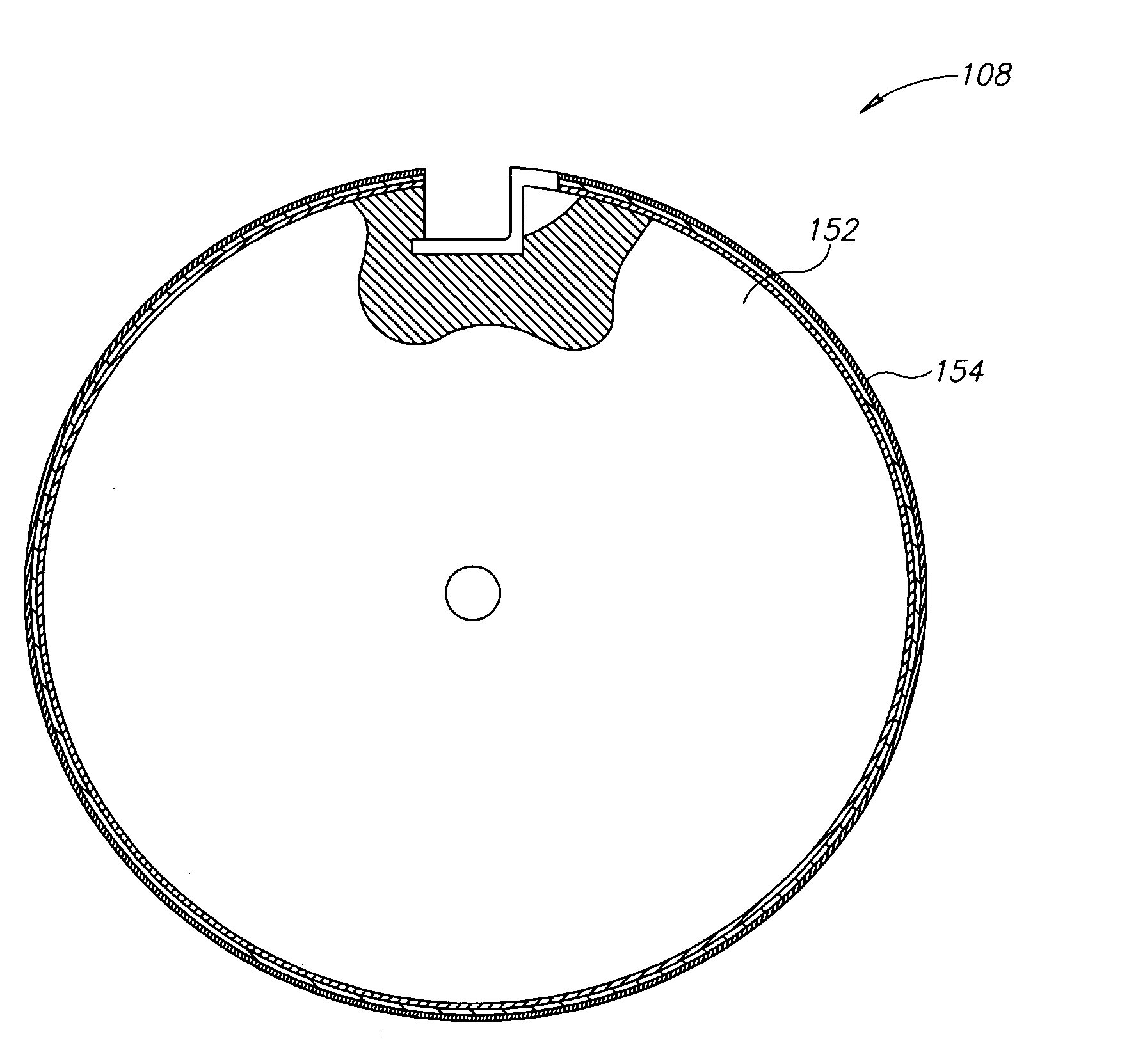
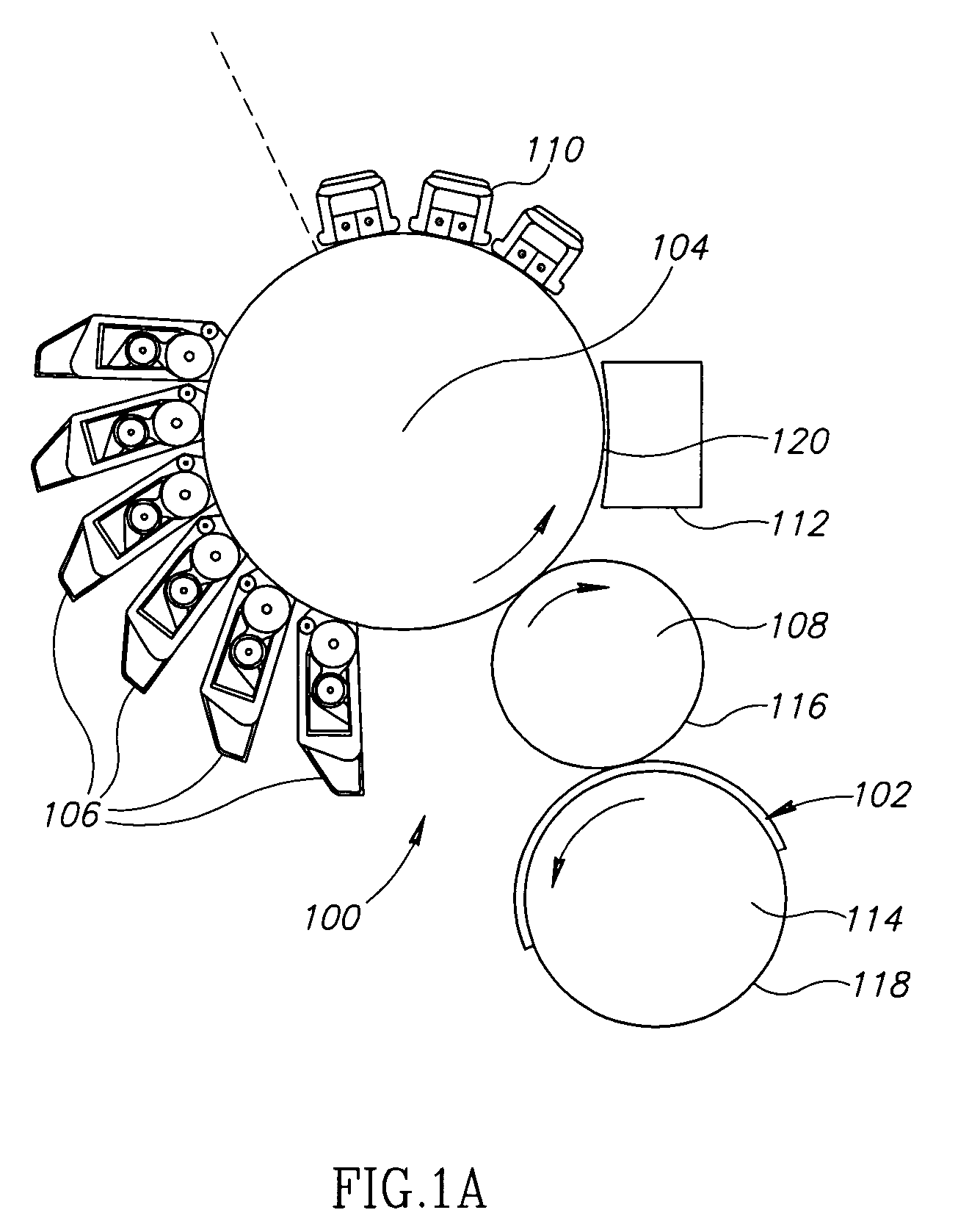
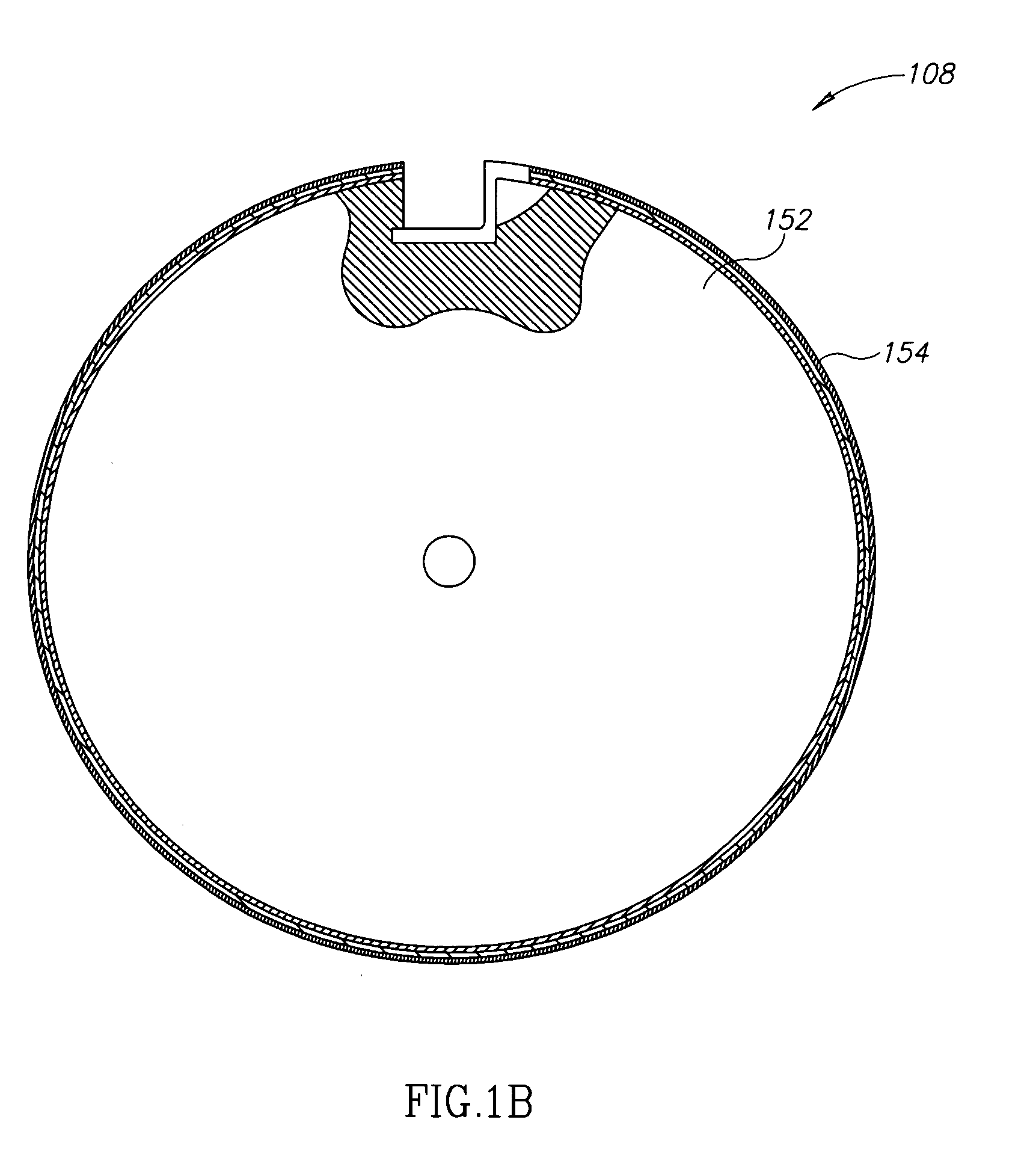
[0028] Referring to FIG. 1A, a basic representation of a print engine 100 is shown, in accordance with an exemplary embodiment of the invention. In an exemplary electro-statographic printing process, a photo imaging plate (“PIP”) 104 or photoreceptor is given a uniform charge by at least one charge unit 110. This uniform charge is selectively discharged to form a latent electrostatic image by, for example a light beam shown as a dashed line, which cans across the PIP as it rotates in the direction shown. The selective discharging on the PIP forms a latent image that corresponds to an image which is to be printed by print engine 100. Liquid toner is optionally discharged from at least one binary image developer (“BID”) 106 which adheres to the appropriately charged areas of PIP 104, thereby developing the latent image. In some exemplary embodiments of the invention, the liquid toner is comprised of at least pigmented toner particles (comprising a polymer and a pigment) and a hydrocarbon liquid. The developed image is first transferred to an ITM 108 and heated on the ITM. The developed image is then transferred, in a second transfer, to a final substrate 102 as described below. U.S. Pat. No. 5,596,396 to Landa et al. and U.S. Pat. No. 5,610,694, to Lior et al., the disclosures of which are herein incorporated by reference, describe methods and apparatuses for binary image development.
[0029] PIP 104 is optionally discharged and cleaned by a cleaning/discharging unit 112 prior to recharging of PIP 104 in order to start another printing cycle. As substrate 102 passes by ITM 108, the image located on ITM 108 surface 116 is then transferred and affixed to substrate 102. Affixation of the image to substrate 102 is facilitated by locating substrate 102 on the surface 118 of impression roller 114, which applies pressure to substrate 102 by compressing it between impression roller 114 and ITM 108 as the image is being transferred to substrate 102. Eventually, substrate 102 bearing the image exits the printer. In some exemplary embodiments of the invention, the printer is a sheet-fed printer. Optionally, the printer is a web-fed printer.
[0030]FIG. 1A also shows a plurality of BID units 106 located in image development area 100. In some exemplary embodiments of the invention, each BID contains a different color toner, for use in producing multi-color images. Optionally, BID units are not used for depositing toner on PIP 104 and other development methods and/or other image formation methods, as known in the art, are used. It should be understood that the foregoing print engine description is provided by way of example only, and that print blankets described herein are suitable for use with a variety of liquid toner print engines.
[0031] Reference is now made to FIG. 1B which is a simplified cross-sectional illustration of ITM 108, including a multi-layered print blanket 154 mounted on a drum 152, in accordance with an exemplary embodiment of the present invention. As is known in the art, ITM 108 is maintained at a suitable voltage and temperature (optionally between 85° C.-200° C.) for electrostatic transfer of a toner image thereto from an image-bearing surface, such as a photoreceptor surface. The image is preferably transferred from ITM 108 onto a final substrate 102, such as paper, optionally by heat and pressure.
[0032] Reference is now made to FIGS. 2A to 2F which schematically illustrate exemplary embodiments of print blankets, in accordance with various embodiments of the invention.
[0033]FIG. 2A illustrates an exemplary embodiment of a print blanket 202 in which no underlayer 216, described below, is provided. In an exemplary embodiment of the invention, an adhesive 204 is optionally used to secure print blanket 202 to drum 152. Optionally, only a portion of print blanket 202 is secured to drum 152 by adhesive. In an exemplary embodiment of the invention, adhesive 204 is the innermost layer of print blanket 202 in relation to drum 152. Optionally, print blanket 202 is mechanically secured to drum 152, for example using the apparatuses and methods described in U.S. Pat. No. 6,551,716 to Landa et al., the disclosure of which is incorporated herein by reference. Optionally, the leading edge of print blanket 202 is held in place by a fixture, such as described in U.S. Pat. Nos. 5,745,829 and 6,551,716. In some embodiments of the invention, if the back surface of the next layer is very smooth and soft enough so that the blanket clings to the drum beneath, no adhesive is necessary, (or the adhesive layer is replaced by a very smooth, soft layer).
[0034] In the exemplary embodiment of the invention depicted in FIG. 2A, adhesive 204 (if present) is covered by a reinforced rubber impregnated fabric layer 206 as known in the art. This layer is similar to a corresponding layer in offset printing blankets. The next outermost layer, in accordance with an exemplary embodiment of the invention, is a compressible layer 208. This layer, which may comprise multiple layers of compressible material, is described in detail in PCT publication WO 97/07433, the disclosure of which is incorporated herein by reference. A conductive layer 210 is provided externally of compressible layer 208 from drum 152, in some exemplary embodiments of the invention. This allows for the application of a voltage between the blanket and a photoreceptor from which the image is to be transferred to aid in transferring the image to the photoreceptor.
[0035] Layers 206-210 are optionally considered the “body” of print blanket 202. Optionally, the body of the print blanket includes an underlayer 216 (FIG. 2B).
[0036] Certain aspects of the present invention, especially the composition of the portion of the print blanket situated below the image transfer layer, are shown and described by way of example only and may vary in accordance with specific requirements and design considerations.
[0037] It should be understood that the above construction of the blanket body can be purely conventional and does not, by itself, differ substantially from prior art blankets for use in electrostatographic printing. For example the material properties (such as hardness), and/or the materials used and/or the thicknesses of the layers may be similar to those used in the prior art including the references incorporated herein. A major innovation in the blankets described herein is in the image transfer layer as described below. Further, the image transfer layer can be used with any heated intermediate transfer member for liquid toner images.
[0038] In an exemplary embodiment of the invention, the outermost layer of print blanket 202 in relation to drum 152 is an image transfer (upper) layer 212. In FIG. 2A, image transfer layer 212 is positioned on conductive layer 210 such that in operation, an image can be transferred to the image transfer layer from an image-bearing surface, such as a photoreceptor surface, and then transferred to a final substrate, such as paper or plastic film.
[0039] In an exemplary embodiment of the invention, image transfer layer 212 is comprised of a fluoroelastomer. Optionally, the fluoroelastomer material is a dipolymer of VF2/HFP. Optionally, the fluoroelastomer material is a terpolymer of VF2/HFP/TFE. Optionally, the fluoroelastomer material is a copolymer of TFE/Propylene and ethylene/TFE/PMVE. Optionally, the fluoroelastomer is a combination of any of the above. Commercially available fluoroelastomer products suitable for use with image transfer layer 212 include the Viton® family of fluoroelastomers by DuPont®, Kalrez®, the Dyneon® family by 3M® and the Technoflon® family by Solvay or FKM. Additives known in the art are optionally added to image transfer layer 212 for properties optimization. For example, carbon black and/or salts are added to optimize the conductivity of the transfer layer by choosing the proper concentration and particle size. Additives like Teflon, silicone and/or others allow optimization of release properties. In some exemplary embodiments of the invention, the elastomer formulation is comprised of no more than 80% fluorine by weight. Optionally, the elastomer formulation is comprised of no more than 71% fluorine by weight. Optionally, the elastomer formulation is comprised of no more than 65% fluorine by weight.
[0040] The inventors have found that the layer should be softer than Shore A 50-60, although softer materials such as Shore A of 40-50 is desirable. Mixtures of different fluoroelastomer elastomer materials may be used to provide a desired softness of the layer.
[0041] Reference is made to FIG. 2C, where in accordance with an exemplary embodiment of the invention, no conductive layer is provided to a print blanket 220. As described below, with respect to FIG. 2E, it has been found that a fluoroelastomer layer such as described herein can be made conductive enough to replace a conventional conductive layer.
[0042] A blanket 222 is shown in FIG. 2D, wherein compressible layer 208 of other embodiments of the invention is replaced by an additional fluoroelastomer layer 226. Blanket 222 thus is provided with two fluoroelastomer layers, an upper, transfer layer 224 and additional layer 226. In some exemplary embodiments of the invention, additional layer 226 is adapted to provide the same functionality as compressible layer 206 found in other exemplary blanket embodiments. Additional layer 226 is comprised of sufficient thickness to provide reliable and/or high quality transfer of an image to a final substrate. Optionally, additional layer 226 is no more than 200 microns thick. Optionally, additional layer is no more than 500 microns thick. In some exemplary embodiments, additional layer 226 is more than 500 microns thick. In some exemplary embodiments of the invention, manufacturing costs are saved by eliminating the need for an additional component material (spongy compression layer).
[0043] Referring to FIG. 2E, an exemplary blanket 230 is shown wherein a main fluoroelastomer layer 232 is used in lieu of image transfer layer 212, conductive layer 210, under layer 216, and/or compressible layer 208. Main fluoroelastomer layer 232 is adapted to perform a variety of functions, in an exemplary embodiment of the invention. For example, main fluoroelastomer layer 232, it has been shown by the inventors, exhibits sufficient electrical conductivity to act in lieu of conductive layer 210. Optionally, additives such as carbon black and/or salts are included in main fluoroelastomer layer 232 to enhance conductivity of layer 232. Optionally, the portion of the main FE layer further from a surface of main FE layer exhibits enhanced conductivity relative to the portion of main FE layer closer to the surface. Additionally, it has been found by inventors that main fluoroelastomer layer 232 exhibits sufficient micro and macro hardness to provide reliable and/or high quality first (from PIP) and second transfer (to final substrate) of an image. In some exemplary embodiments of the invention, main fluoroelastomer layer 232 is no more than 100 microns thick. Optionally, main fluoroelastomer layer 232 is no more than 500 microns thick. In some exemplary embodiments of the invention, main fluoroelastomer layer 232 is more than 500 microns thick
[0044]FIG. 2F shown an exemplary blanket 240 wherein a hard under layer 242 is provided. In an exemplary embodiment of the invention, hard under layer 242 is provided to enhance application of blanket 240 pressure during image transfers. In an exemplary embodiment of the invention, hard under layer 242 is comprised of Kepton®. In some exemplary embodiments of the invention, hard under layer 242 is no more than 200 microns thick. Optionally, hard under layer 242 is no more than 100 microns thick. In some exemplary embodiments of the invention, hard under layer 242 is between 5-25 microns thick.
Improvement of Image Quality
[0045] Silicone based image transfer layers, as are known in the art, swell when used in conjunction with a liquid toner. Mineral oils and other liquid components of liquid toner are absorbed by the silicone based image transfer layers. As a result, image quality can be degraded when the image is finally transferred from the ITM to the final substrate. This image quality degradation manifests itself in a plurality of ways. The first is that when a print blanket swells, its surface begins to vary in glossiness. Most images do not require 100% toner coverage. For example, there are spaces in between words, letters, and paragraphs in a printed document and spaces between dots in a half-tone image. These spaces do not require the placement of toner on the image transfer layer in order to manifest themselves on a final substrate. In those areas where toner is not transferred to the image transfer layer, there is little if any swelling, whereas where there is liquid toner present, swelling occurs. This disparity in swelling results in a visible differential in gloss in the toner and non-toner areas of the final substrate for subsequent images. That is, those areas where swelling occurred before transfer of the present image exhibit a different glossiness than those areas which remained liquid toner free in the previous image. Differential gloss on the final substrate is often considered a degradation of the image. Use of a fluorinated elastomer in the image transfer layer of a print blanket reduces the swelling of the print blanket in the presence of liquid toner. As a result, differential gloss is reduced and image quality is improved.
[0046] In an exemplary embodiment of the invention, electrostatic printing is conducted using an image transfer layer with less favorable release properties to hot melt adhesives, such as liquid toner, in the operational range of 85° C.-200° C., than the silicone materials normally used. In addition, it is also noted that at the operation temperature of 85° C.-200° C., fluoroelastomer based image transfer layers in print blankets decrease in material hardness, thus enabling the image transfer layer to better conform to the substrate surface topography and transfer a more true image. In some exemplary embodiments of the invention, the image transfer layer exhibits a Shore A hardness of no more than 65 at room temperature. Optionally, the image transfer layer exhibits a Shore A hardness of no more than 45 at room temperature. Optionally, the image transfer layer exhibits a Shore A hardness of between 25 and 35 at room temperature. In an exemplary embodiment of the invention, the hardness of the fluoroelastomer layer decreases with increasing temperature to 110-150° C. by 10-15 Shore A. In such an embodiment, hardness measurements of 65 Shore A material at room temperature show 45-50 Shore A at this temperature.
[0047] Image quality is also improved, in some exemplary embodiments of the invention, by using a fluorinated elastomer based image transfer layer to maintain a liquid layer between the transfer layer and the heated toner particles in the liquid toner formulation. Referring to FIG. 3, a cross-sectional view of liquid toner 300 coating an image transfer layer 302 of a print blanket 308 is shown. In conventional electrostatic printing, drum 152 is typically heated by an internal halogen lamp heater or other heater to aid transfer of the image to the image transfer layer 302 and therefrom to the final substrate, as is well known in the art. As is described above, operational temperatures for the heated ITM are often in the range of 85° C.-200° C. It should be noted, however, that the degree of heating often depends on the characteristics of the toner and/or ink used.
[0048] The high temperature of the ITM causes the toner particles of the liquid toner formulation to become heated and subsequently to fuse. In the regions of the liquid toner closer to the ITM, a layer of liquid 304 is created which is typically comprised of carrier liquid and oils associated with the liquid toner formulation. Due to the high temperatures, the carrier liquid associated with the liquid toner are prone to evaporation. When silicone materials are used for the transfer layer, the portion of the liquid layer 304 which isn't evaporated by heat is absorbed by the image transfer layer. This causes a hot melt adhesive layer 306 of the liquid toner to come into direct contact with image transfer layer 302. This contact may result in some portion of hot melt adhesive layer 306 sticking to image transfer layer 302 and not transferring to the final substrate. This sticking results in degraded image quality since some of the image remains on image transfer layer 302. This also requires that the transfer layer be abhesive to the hot melt adhesive polymer that is the basis for the toner. This results in the requirement that the coating be abhesive to the hot melt adhesive toner, a difficult condition to achieve and even more difficult to maintain.
[0049] By using a carrier liquid resistant fluoroelastomer based image transfer layer, such as those described herein, absorption of the liquid layer 304 between hot melt adhesive layer 306 and image transfer layer 302 is diminished. This results in a substantially intact liquid layer 304 which acts as a release facilitator acting when the image (which is now represented by hot melt adhesive layer 306) is transferred to the final substrate. Surface roughness of the image transfer layer plays a factor in the maintenance of liquid layer 304. For example, if the surface of image transfer layer 302 has high peaks and valleys, it is likely that liquid layer 304 will deposit itself into the valleys, leaving the peaks exposed to direct contact with hot melt adhesive layer 306. If the surface is smooth however, there is less of a chance of hot melt adhesive layer 306 contacting image transfer layer 302. Therefore in an exemplary embodiment of the invention, a print blanket is provided which has an image transfer layer with an RMS surface roughness of no more than 700 Å or 500 Å. Optionally, the image transfer layer has an RMS roughness of no more than 250 Å or 150 Å. Optionally, the image transfer layer has an RMS roughness of between 40 and 50 Å.
[0050] It should be especially noted that print blankets containing fluoroelastomer image transfer layers, such as those described herein, are advantageous over conventional silicone based print blankets because they do not have to be as abhesive since in normal operation fluids rarely penetrate to the body of the blanket.
Increased Lifespan
[0051] In an exemplary embodiment of the invention, print blanket life is increased by using a non-silicone fluoroelastomer based image transfer layer thereon. As described herein, conventional silicone based image transfer layers absorb liquids associated with liquid toner formulations. This absorption and subsequent evaporation of liquid causes a cycle of expansion and contraction in the image transfer layer which is both unremitting and quick in nature. As a result, the mechanical properties of silicon based image transfer layers degrade over time, necessitating frequent replacement of the print blanket. In addition to the complications, which arise as a result of the cycles of expansion and contraction, absorption of liquid by the image transfer layer reduces its strength and its resistance to damage.
[0052] Fluorine based image transfer layers, however, resist the absorption of carrier liquid from liquid toners. This resistance manifests itself in less expansion and contraction during the course of its lifetime. The result of less transfer image layer flexing is the increased retention of mechanical properties, including strength and damage resistance, and hence usable lifespan.
Exemplary Method of Manufacture
[0053] In an exemplary embodiment of the invention, an image transfer layer is formed on a smooth release coated sheet, Teflon sheet and/or metalized Mylar® sheet. Mylar® is optionally used due to its smoothness. In an exemplary embodiment of the invention, the face of the image transfer layer that is proximal to the Mylar® sheet is the face that is used on the outside of the print blanket. Meanwhile, the face of the image transfer layer that is away from the Mylar® sheet during manufacture is the face that is nearest the body of the print blanket when in operation. In an exemplary embodiment of the invention, producing a fluoroelastomer layer as a roll and laminating the layer on top of the blanket in a continuous process reduces the cleanliness requirements of the manufacturing environment. In some exemplary embodiments of the invention, there is no need to cut blankets for curing due to the unitary and continuous blanket body construction.
[0054] The present invention has been described using non-limiting detailed descriptions of embodiments thereof that are provided by way of example and are not intended to limit the scope of the invention. It should be understood that features and/or steps described with respect to one embodiment may be used with other embodiments and that not all embodiments of the invention have all of the features and/or steps shown in a particular figure or described with respect to one of the embodiments. Variations of embodiments described will occur to persons of the art. Furthermore, the terms “comprise,”“include,”“have” and their conjugates, shall mean, when used in the disclosure and/or claims, “including but not necessarily limited to.”
[0055] It is noted that some of the above described embodiments may describe the best mode contemplated by the inventors and therefore may include structure, acts or details of structures and acts that may not be essential to the invention and which are described as examples. Structure and acts described herein are replaceable by equivalents, which perform the same function, even if the structure or acts are different, as known in the art. Therefore, the scope of the invention is limited only by the elements and limitations as used in the claims.

PUM

no PUM

Description & Claims & Application Information

We can also present the details of the Description, Claims and Application information to help users get a comprehensive understanding of the technical details of the patent, such as background art, summary of invention, brief description of drawings, description of embodiments, and other original content. On the other hand, users can also determine the specific scope of protection of the technology through the list of claims; as well as understand the changes in the life cycle of the technology with the presentation of the patent timeline. Login to view more.

Similar technology patents

Ocarinas with an inner liner and an outer shell

InactiveUS6872876B2Prevent excessive condensationFacilitate manufacturingPercussion musical instrumentsOcarinasAirflowEngineering
Owner:MOUNTAIN OCARINAS

Classification and recommendation of technical efficacy words

Why Eureka
Try Eureka