[0008] The present invention has been made in view of the above-mentioned problems and circumstances. Thus, it is an object of the invention to provide a connecting structure for connecting together the rotation operation shaft and operation knob of the electric apparatus, the connecting structure being arranged such that, when division grooves are formed in the cylindrical part of the rotation operation shaft to thereby enhance the flexural deformation property of the cylindrical part, there are taken measures capable of balancing the flexural deformation properties of the respective portions of the cylindrical part in the
peripheral direction thereof with each other, thereby preventing the tight fit engaged portions between the cylindrical part of the rotation operation shaft and the shaft part of the operation knob from being out of concentricity with respect to each other; and also, when enhancement in the flexural deformation property of the cylindrical portion is attained, it is possible to positively prevent the occurrence of a situation that, the cylindrical and shaft parts are easy to idle with respect to each other.
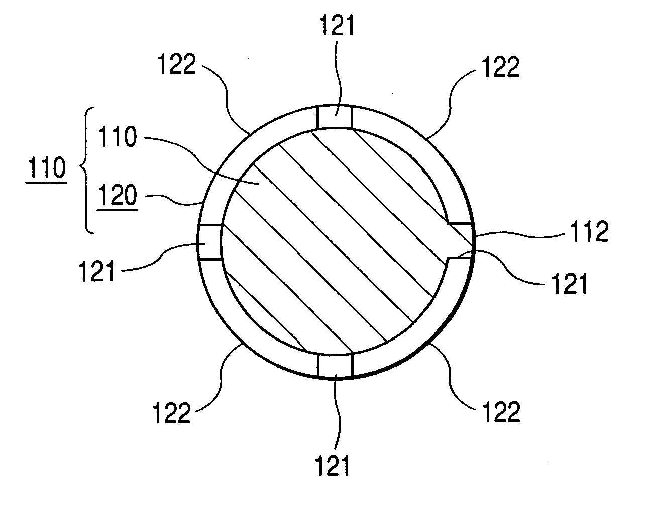
[0009] A connecting structure for connecting together the rotation operation shaft and operation knob of an electric apparatus according to the invention is a connecting structure for connecting together the rotation operation shaft and operation knob of an electric apparatus, which is arranged such that a cylindrical part formed in the rotation operation shaft and a shaft part formed in the operation knob are connected together in a tight fit manner to thereby be able to adjust a fit allowance between them increasingly or decreasingly, wherein division grooves respectively extending in the axial direction of the cylindrical part formed of resin are formed in two or more portions of the cylindrical part at equal angle intervals in the peripheral direction of the cylindrical part to thereby be able to not only enhance the flexural deforming property of the cylindrical part but also secure the mutual concentricity between the cylindrical part and the shaft part formed of resin; and also wherein at least one of the division grooves is used as a key groove with which is fitted a key portion formed in the outer peripheral portion of the shaft part to thereby be able to prevent the cylindrical and shaft parts from rotating with respect to each other.
[0010] According this structure, the formation of the division grooves in two or more portions of the cylindrical part can enhance the flexural deformation property of the cylindrical part as well as, owing to the fact that the division grooves are formed in two or more portions of the cylindrical part at equal angle intervals in the peripheral direction of the cylindrical part, the flexural deformation properties of the respective portions of the cylindrical part in the peripheral direction thereof are allowed to balance out. This can prevent the occurrence of a situation that the cylindrical part and the shaft part tight fit engaged with the cylindrical part are out of concentricity with respect each other and are thereby inclined with respect to each other. Also, since at least one of the division grooves is used as a key groove with which is fitted a key portion formed in the outer peripheral portion of the shaft part, the cylindrical part and shaft part are prevented from rotating with respect to each other, thereby being able to prevent them from idling with respect to each other.
[0011] According to the invention, by setting even the thicknesses of two or more arbitrary portions of the cylindrical wall of the cylindrical part in the peripheral direction thereof, it is possible to employ a structure that the elastic constants of the respective cylindrical wall pieces divided and formed by the division grooves are set even; and, employment of this structure can make it easy for the flexural deformation properties of the respective portions of the cylindrical part in the peripheral direction thereof to balance out.
[0012] According to the invention, it is possible to employ a structure in which the above-mentioned division grooves are formed in four portions of the cylindrical part at equal angle intervals in the peripheral direction thereof and one of the division grooves is used as a key groove with which is fitted a key portion formed in one portion of the outer peripheral portion of the shaft part. According to this structure, the lowered strength of the cylindrical part caused by the formation of the division grooves is not so great. Thanks to this, the rotational movement of the operation knob manually operated can be positively transmitted to the rotation operation shaft through the tight fit engaged portions between the shaft part and cylindrical part.
[0014] As described above, according to the invention, not only the flexural deformation properties of the respective portions of the cylindrical part in the peripheral direction thereof balance out to thereby make it difficult for the tight fit engaged portions between the cylindrical and shaft parts to be out of concentricity, but also, when the flexural deformation property of the cylindrical part is enhanced, it is possible to positively prevent the occurrence of a situation that the cylindrical and shaft parts are easy to idle with respect to each other. Therefore, even when the fit allowances of the two parts are adjusted increasingly or decreasingly in the connected portions between the cylindrical and shaft parts connected together in a tight fit manner to thereby absorb variations in the mounting precision of the rotation operation shaft, the operation knob is prevented from being inclined so that the operation efficiency of the operation knob can be kept well. Also, the
mutual position precision between the operation knob and the box body of the electric apparatus can be kept in a proper level. Further, according to the invention, since it is possible to employ the simple structure in which the division grooves are formed in the cylindrical part and the key portion is formed in the shaft part, the invention is advantageous in
mass production and also can prevent an increase in the number of parts to thereby prevent the assembling efficiency of the invention from being impaired.

