Display device

US20070021007A1Active Publication Date: 2007-01-25SAMSUNG DISPLAY CO LTD

Image

  • Display device
  • Display device
  • Display device

Examples


Embodiment Construction

[0032] A display device according to exemplary embodiments of the present invention will now be described with reference to the accompanying drawings. A liquid crystal display panel is illustrated as an embodiment of a panel assembly employed for the display device in the accompanying drawings, which exemplifies and does not limit the present invention.

[0033] A display device having an edge type backlight assembly is illustrated as an embodiment of the present invention in the accompanying drawings, which exemplifies and does not limit the present invention.

[0034] In the drawings, the same reference numerals designate the same or like elements throughout the specification.

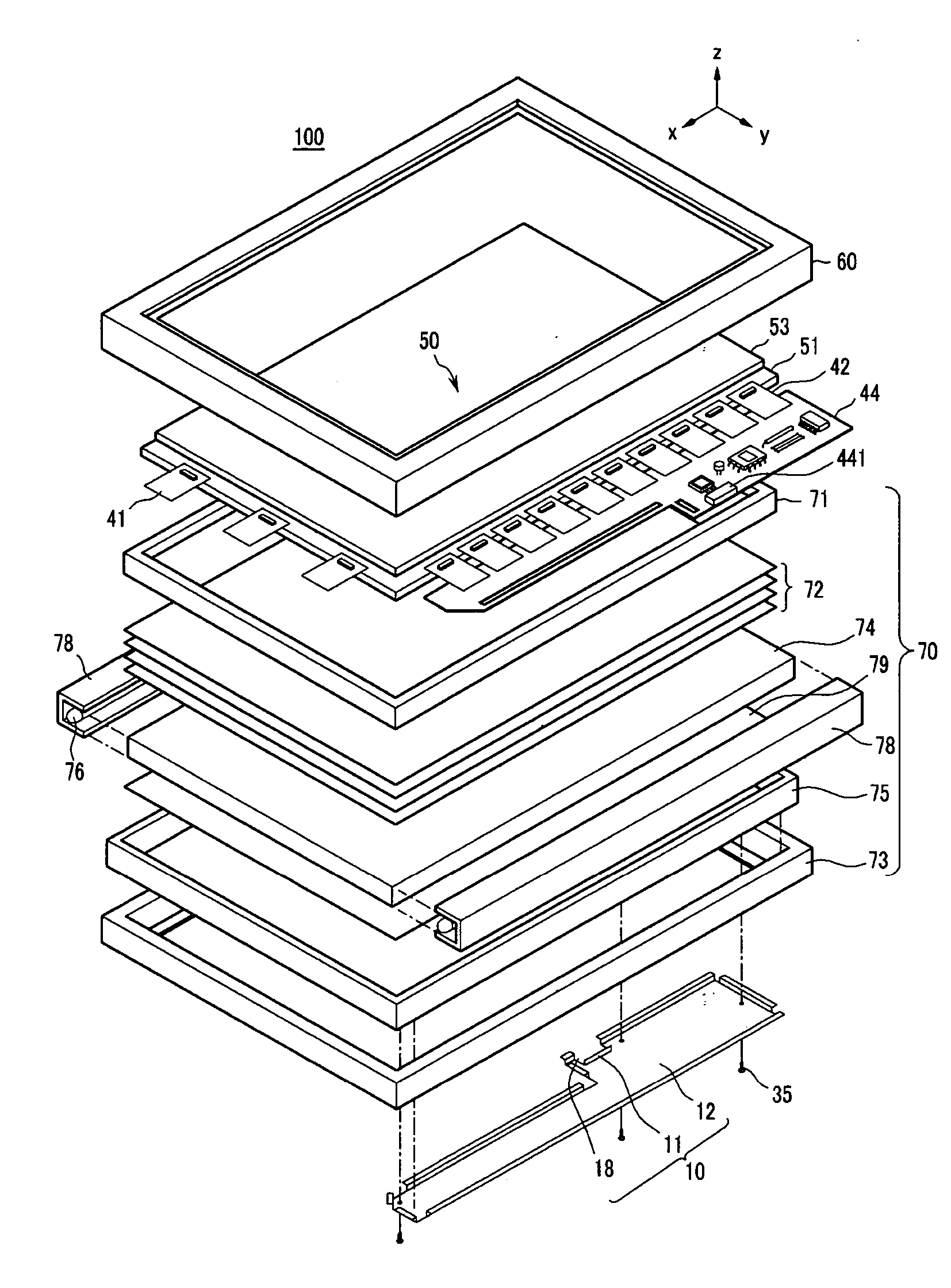
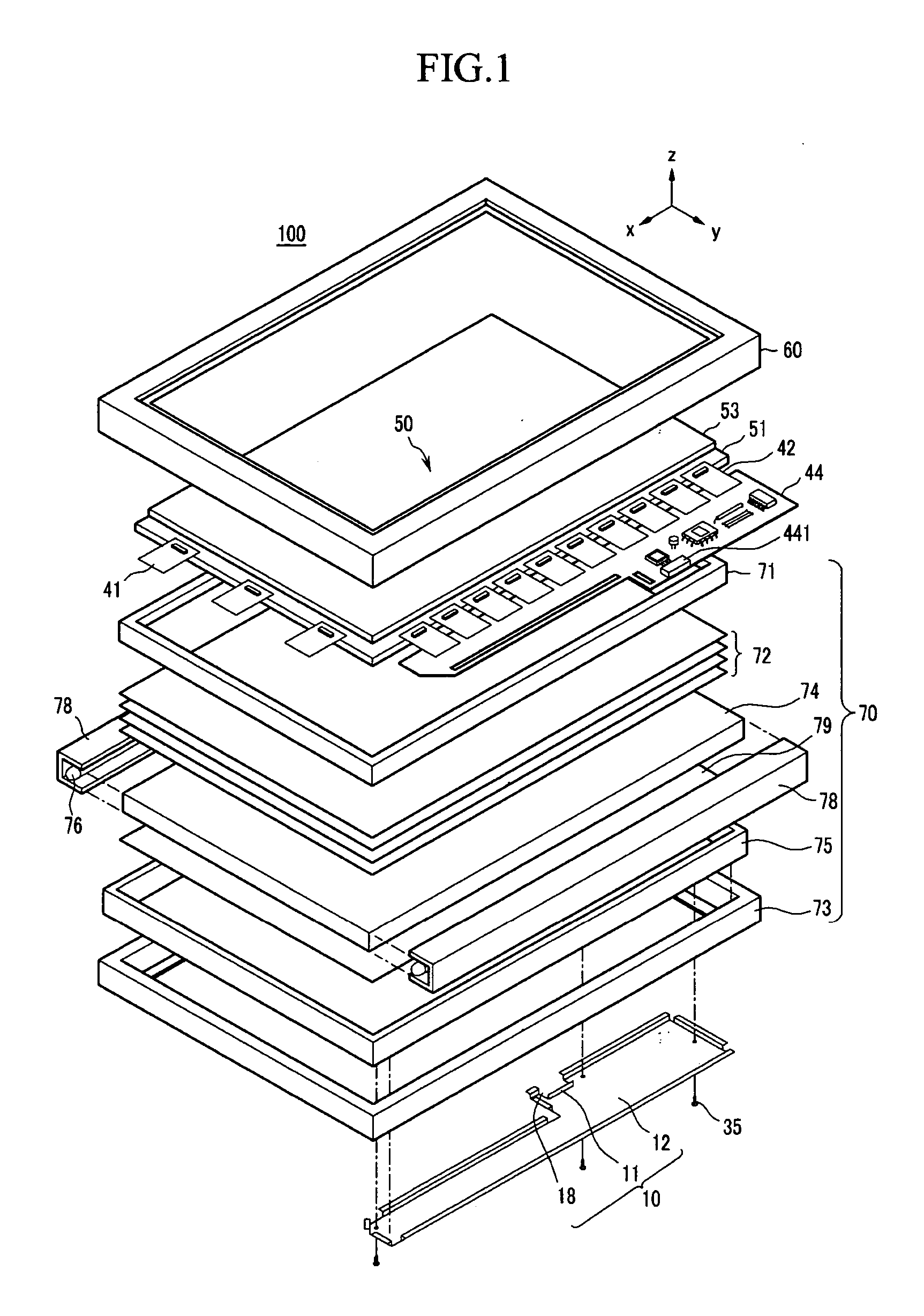
[0035] As shown in FIG. 1, according to an embodiment of the present invention, a display device 100 includes a backlight assembly 70 for providing light and a panel assembly 50 for displaying an image upon receiving light. The display device 100 additionally includes a front support member 60 for fixedly suppor...


PUM


Abstract

A display device includes a panel assembly for forming an image, a printed circuit board (PCB) connected with the panel assembly and having a connector; a support member for supporting the panel assembly and having the PCB installed on a rear surface thereof, and a cover member combined with the support member, covering the PCB, and having an opening exposing the connector. A fixing part formed at the opening of the cover member fixes the connector to the PCB.

Description

CROSS-REFERENCE TO RELATED APPLICATION [0001] This application relates to Korean Patent Application No. 10-2005-0044640 filed in the Korean Intellectual Property Office on May 26, 2005, the entire contents of which are incorporated herein by reference. BACKGROUND OF THE INVENTION [0002] (a) Field of the Invention [0003] The present invention relates to a display device, and more particularly, to a display device with a structure of a cover member that covers a printed circuit board (PCB) providing a drive signal to a panel assembly. [0004] (b) Description of Related Art [0005] As semiconductor technologies have advanced, display devices, such as liquid crystal displays (LCD), have been developed to be small and light weight with high performance. [0006] Given the size, weight, and performance, e.g.,. low power consumption, characteristics of LCDs, LCDs have been increasingly used as a substitute for conventional cathode ray tubes (CRT). [0007] In light-receiving (non-emissive) LCD d...

Claims


Application Information

Patent Timeline
25 Jan 2007
Publication
US20070021007A1
IPC
H01R9/03
CPC
G02F1/13452; H01R12/7076; G02F2001/133334; G02F1/133334; G02F1/1333
Inventors
PARK, HYOUNG-JUN