Capacitive lock switch

a technology of capacitive lock switch and lock switch, which is applied in the direction of electronic switching, contact mechanism, pulse technique, etc., can solve the problems of increasing battery consumption, unnecessary consumption of power and/or other inconveniences, and increasing battery consumption

Inactive Publication Date: 2007-02-01
STANLEY ELECTRIC CO LTD
View PDF10 Cites 37 Cited by
  • Summary
  • Abstract
  • Description
  • Claims
  • Application Information

AI Technical Summary

Benefits of technology

[0014] The disclosed subject matter provides a capacitive lock switch that, in accordance with an aspect of the subject matter, can include: a metallic electrode arranged inside or in the vicinity of a door handle; a converter circuit operative to convert a variation in capacitance associated with the metallic electrode into an electrical parameter; a decision circuit operative to detect a level variation in the electrical parameter; and a time constant circuit operative to measure the time of the level variation to provide a lock signal on measurement of the variation in capacitance over a certain time.

Problems solved by technology

In such a system, the vehicle tends to transmit the electromagnetic wave for a long time, and sometimes infinitely, easily resulting in battery exhaustion and / or other inconveniences.
In such a case, the transceiver operates and emits the electromagnetic wave, which uselessly consumes power and places a burden on the battery.
In this method, the transmitter on the vehicle tends to operate longer, and results in an increase in battery consumption.
Accordingly, the transceiver mounted on the vehicle interprets the trigger operation as a request for unlocking or locking and performs transmission to the entry key, leading to consumption of the battery, or the power supply in the vehicle.
When the owner carrying the entry key occasionally stands near the vehicle, another person may touch the handle body, or a rainfall may occur.
Also in such a case, an erroneous operation may unlock the vehicle and start the engine or perform other functions, regardless of the will of the owner / driver.

Method used


Image

  • Capacitive lock switch
  • Capacitive lock switch
  • Capacitive lock switch

Examples


Embodiment Construction

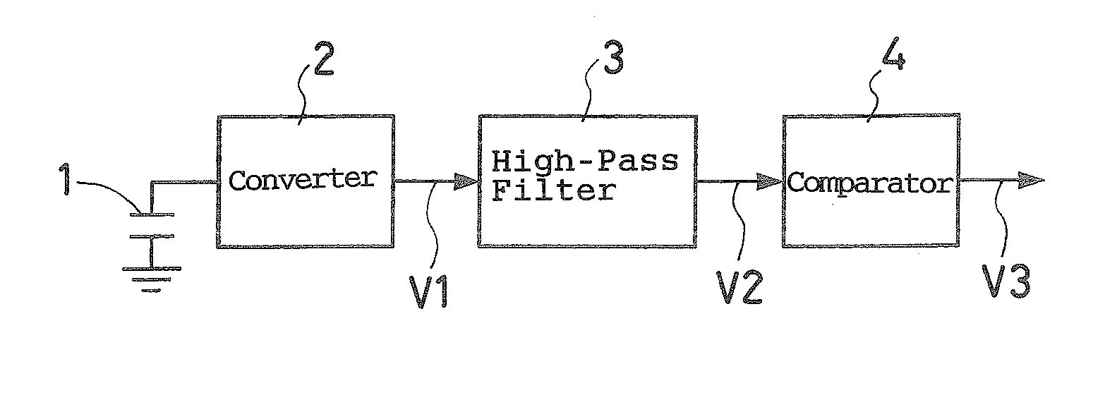
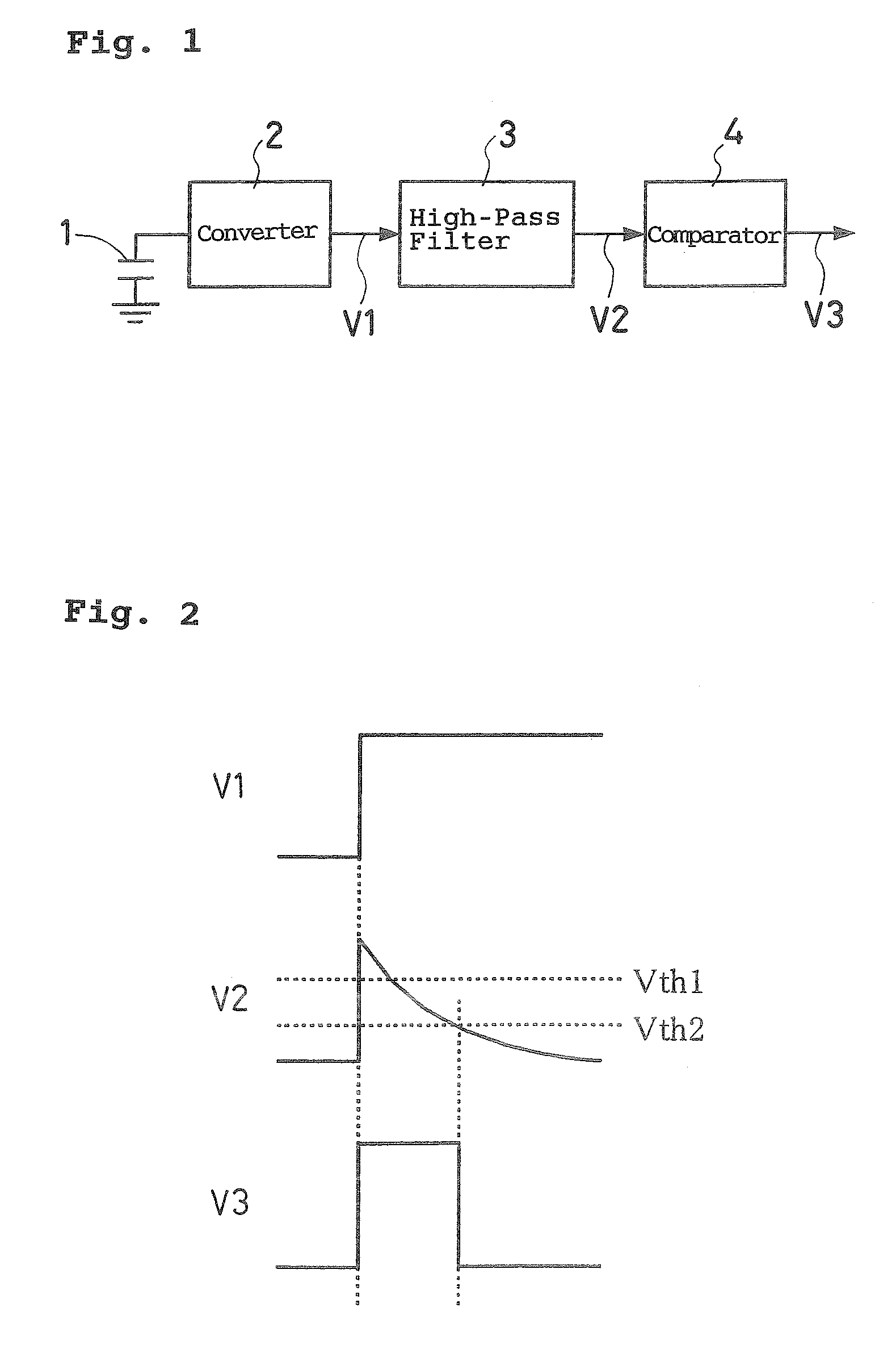
[0029] The disclosed subject matter will be described next in detail based on the exemplary embodiments shown in the figures. The basic detector circuit of the capacitive type lock switch can be configured as shown in FIG. 1. In this case, a capacitance 1 is the target capacitance provided, for example, in a door handle, latch, or the like of the vehicle. A converter 2 is a circuit operative to convert a value of the capacitance 1 into a voltage or a digital signal. A high-pass filter 3 is a circuit operative to remove a DC component from an output signal from the converter 2. A comparator 4 is a circuit operative to binarize an output signal from the high-pass filter 3.

[0030] Consideration is now given to the case where a human body or the like touches the capacitance 1 to increase the capacitance 1 in FIG. 1. In this case, an output V1 from the converter 2 also increases. If the rate of increase in the capacitance 1 is sufficiently higher than a time constant of the high-pass fil...


PUM


Abstract

A capacitive lock can include various circuits that allow it to operate more efficiently and with greater accuracy. For example, when a user continuously touches a door handle for a certain time duration, a sensor can be configured to retain a variation in capacitance. When the door handle is continuously touched, a time constant circuit (timer) can be provided inside the entry system and measures the contact time and unlocks a door on the assumption that the user has a will to unlock and/or operate the vehicle or other apparatus.

Description

[0001] This application claims the priority benefit under 35 U.S.C. § 119 of Japanese Patent Application No. 2005-221150 filed on Jul. 29, 2005, which is hereby incorporated in its entirety by reference. BACKGROUND [0002] 1. Technical Field [0003] The disclosed subject matter relates to a key named smart entry capable of locking / unlocking without directly operating the key when it is carried. More particularly, it is associated with an arrangement of the smart entry system for use in vehicles. [0004] 2. Description of the Related Art [0005] In a smart entry key having a simple arrangement, an electromagnetic wave is always transmitted from the vehicle to the smart entry key carried by the user. When the user carrying the smart entry key approaches a locked door, trunk, or the like, the key receiving the electromagnetic wave from the vehicle transmits a code number. In this case, the door is unlocked if the code number matches. [0006] When the user moves away from the vehicle and it ...

Claims


Application Information

Patent Timeline
Patent Type & Authority Applications(United States)
IPC IPC(8): H01H3/16
CPCE05B81/78H03K2217/960715H03K17/962
Inventor ISHIKAWA, KIYOMITSUHIROSE, YOICHI
Owner STANLEY ELECTRIC CO LTD
Why Eureka
Try Eureka