Optical disk drive

a technology of optical disk drive and optical disk, which is applied in the field of optical disk drive, can solve the problems of large power consumption during operation and the enlargement of the circuit scal

Inactive Publication Date: 2007-02-01
KK TOSHIBA
View PDF0 Cites 12 Cited by
  • Summary
  • Abstract
  • Description
  • Claims
  • Application Information

AI Technical Summary

Problems solved by technology

However, since a circuit scale enlarges owing to complexity of the constitution of the PRML signal processing circuit as compared with the conventional slice circuit, a way to reduce a power consumption during operation is a large technical problem.

Method used


Image

  • Optical disk drive
  • Optical disk drive
  • Optical disk drive

Examples


first embodiment

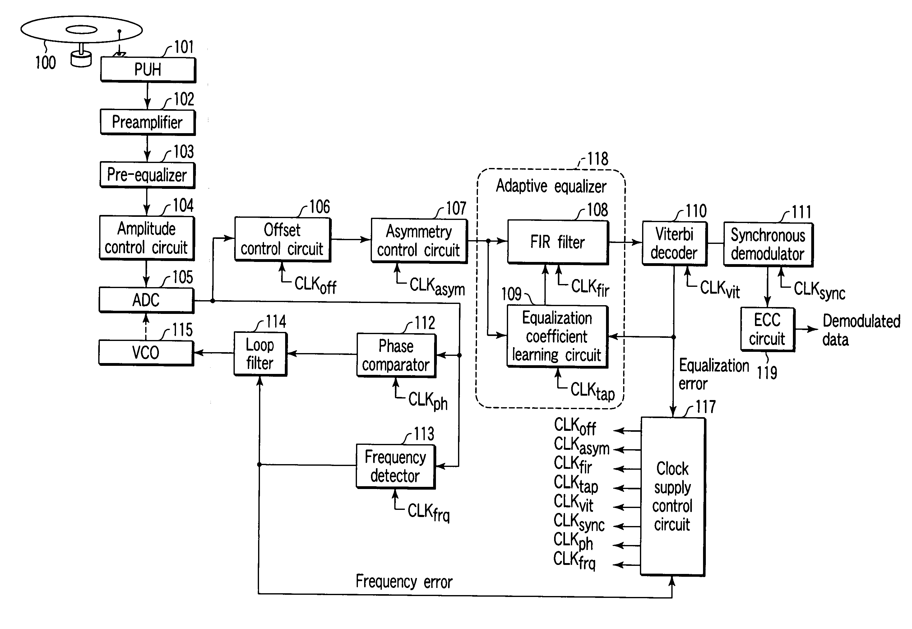
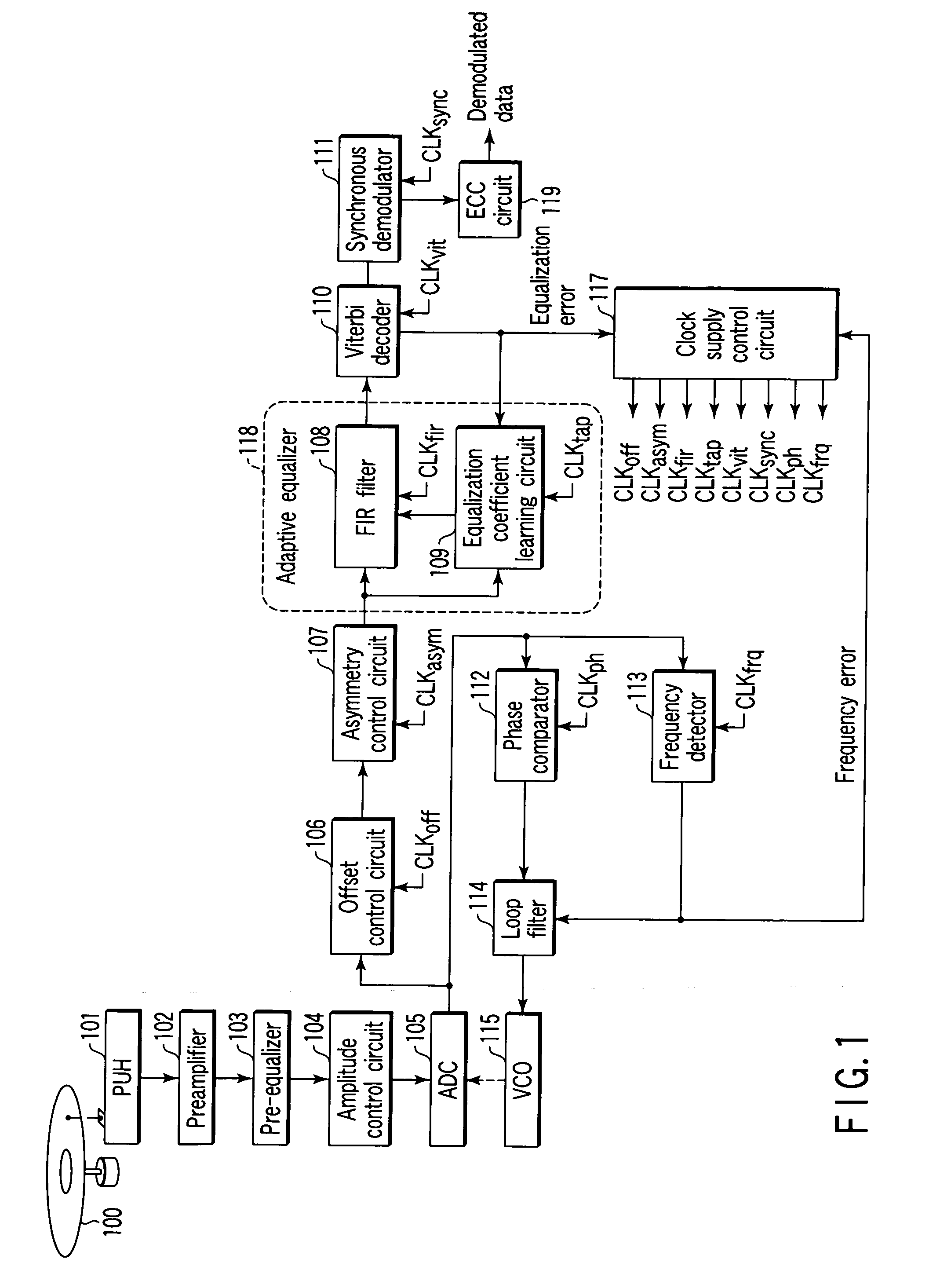
[0020] Various embodiments according to the invention will be described hereinafter with reference to the accompanying drawings. In general, according to one embodiment of the invention, to achieve the problem, an optical disk drive of the present invention is an optical disk drive which decodes data recorded in an optical disk by use of PRML signal processing, and includes: an optical pickup which irradiates the optical disk with laser light and which detects reflected light from the optical disk to supply a reproduction signal; an analog to digital converter which converts, into a digital value, a level of the reproduction signal supplied from the optical pickup; a voltage control oscillator which supplies a clock for conversion to the analog to digital converter; a frequency detector which detects a frequency error between a frequency of the reproduction signal supplied from the analog to digital converter and a frequency of the clock for conversion; a phase comparator which dete...

second embodiment

[0048] Next, there will be described a clock supply control in an adaptive equalizer 118 during steady reproduction in the present invention.

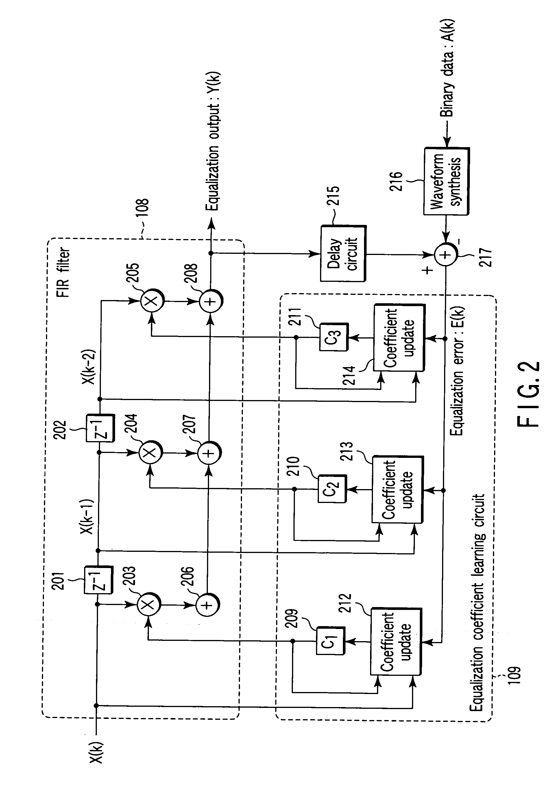
[0049] As described above, the adaptive equalizer 118 produces an effect that the equalization error value is fed back to thereby bring an input signal to a PR characteristic, and an error ratio in a Viterbi decoder 110 is lowered. The adaptive equalizer 118 can especially compensate for frequency fluctuations or nonlinear distortions such as tangential tilts. However, in a state in which a signal quality level of the input signal is high, and an absolute value of an equalization error value is small, an equalization coefficient value of the adaptive equalizer 118 does not have to be updated. Even if an output is emitted by fixed equalization, an error ratio is not largely deteriorated.

[0050] A clock supply control circuit 117 obtains the equalization error value from the Viterbi decoder 110, and processes this equalization error value to gene...

third embodiment

[0058]FIG. 7 shows a constitution diagram of the

[0059] In FIG. 7, there is further added a steady reproduction judgment unit 116 which judges the level of the stability of the steady reproduction state. The steady reproduction judgment unit 116 judges the level of the stability from a sync detection result of a synchronous demodulator 111.

[0060] An operation of this steady reproduction judgment unit 116 will be described hereinafter. In an only case where it is detected that sync codes input every 1116 bits completely agree with one another, a completely sync detection pulse SD is generated, and transmitted to the steady reproduction judgment unit 116. The steady reproduction judgment unit 116 checks continuity of this completely sync detection pulse SD. When the pulses continue successively, it is judged that a reproducing operation is steady, and a judgment level is raised.

[0061] In a case where a signal quality level is deteriorated halfway, the sync codes do not completely agr...


PUM

PropertyMeasurementUnit
frequencyaaaaaaaaaa
phase erroraaaaaaaaaa
oscillation frequencyaaaaaaaaaa

Abstract

According to one embodiment, a frequency detector detects a frequency error between a frequency of a reproduction signal supplied from an analog to digital converter and a frequency of a clock for conversion. A loop filter controls an oscillation frequency of a voltage control oscillator based on the frequency error and a phase error detected by a phase comparator. An adaptive equalizer equalizes a waveform of the reproduction signal supplied from the analog to digital converter to obtain a response of a predetermined PR class. A Viterbi decoder decodes the waveform equalized signal into binary data by maximum likelihood sequence estimation. A clock supply control circuit stops supply of a clock to at least the phase comparator, the adaptive equalizer and the Viterbi decoder in a case where the frequency error is larger than a designated error.

Description

CROSS-REFERENCE TO RELATED APPLICATIONS [0001] This application is based upon and claims the benefit of priority from Japanese Patent Application No. 2005-220359, filed Jul. 29, 2005, the entire contents of which are incorporated herein by reference. BACKGROUND [0002] 1. Field [0003] One embodiment of the invention relates to an optical disk drive which decodes data recorded in an optical disk, by use of partial response maximum likelihood (PRML) signal processing. [0004] 2. Description of the Related Art [0005] Examples of a recording medium with respect to which digital data can be recorded and reproduced include an optical disk represented by a DVD. For example, in a DVD-RAM which is one of the DVDs, a signal recording layer is disposed, this signal recording layer is irradiated with laser light having appropriate energy to thereby change a crystalline state of the recording layer, and the digital data is recorded. When this recording layer is irradiated with the laser light havi...

Claims


Application Information

Patent Timeline
Patent Type & Authority Applications(United States)
IPC IPC(8): G11B20/10
CPCG11B20/10009G11B20/10046G11B2020/1863G11B20/10425G11B20/10222
Inventor TATSUZAWA, YUKIYASUYAMAKAWA, HIDEYUKIOTAKE, KOICHIKANESHIGE, TOSHIHIKOMORINO, HIROAKI
Owner KK TOSHIBA
Why Eureka
Try Eureka