Snapshot of noise and acoustic propagation

a technology of acoustic propagation and noise, applied in the field of noise and acoustic propagation, can solve the problems of less mobile, non-ideal environment, and inability to analyze the characteristics of a target source using the shels method, and achieve the effect of eliminating background sound, less mobile, and accurate and repeatable results

Inactive Publication Date: 2007-02-01
WAYNE STATE UNIV
View PDF6 Cites 1 Cited by
  • Summary
  • Abstract
  • Description
  • Claims
  • Application Information

AI Technical Summary

Benefits of technology

[0008] Unlike the original HELS method, the present invention describes the sound field using two sets of expansion functions, one for direct sound radiation from a target source and the other for the background sounds that travel in the opposite direction as that of direct sound from the target. The coefficients associated with these expansion functions are determined in a similar manner as those in the HELS method. Once the expansion coefficients are determined, however, we display the sound spectrum and SPL values using the set of expansion functions that describe direct sound radiation from a target. In this way, we can effectively eliminate background sounds produced by neighboring sources and reflections from nearby surfaces.
[0010] By encircling a target source, we can effectively eliminate the background sound coming from all directions. Since there are no sound source and reflecting surface other than the target inside a microphone ring, we can treat the sound emitted from a target as the direct sound traveling toward microphones and sounds radiated from neighboring sources and reflected from nearby surfaces as background sounds traveling in the opposite direction as that of direct sound. This scenario matches perfectly the acoustic model adopted in the present invention. Hence, this approach can yield accurate and repeatable results and is very robust in a non-ideal environment. However, it requires setting up a microphone array and fixing it to a target, thus it is less mobile.
[0011] By using a microphone probe, we can take a measurement anywhere. Therefore, the second approach is very convenient, flexible, easy to use in practice, and requires no set up of the measurement device. However, its accuracy may depend on the location of the background noise sources. If background noise sources are behind a target source but all in front of the microphone probe, the microphone probe will capture sound from the target source and that from background noise sources, all traveling in the same direction. In other words, the direct sound in the acoustic model will include sounds from the target and background noise sources. Meanwhile, the sounds traveling in the opposite direction are minimal. Under this condition, there is no way to separate the sound from the target source and those from background sounds.
[0012] However, when background noise sources are behind the microphone probe and the target is in front of the microphone probe such that the direct sound from the target travels in the opposite direction as those of background sounds, we can extract the sound emitted from a target accurately from the overall acoustic field. Consequently, in using a microphone probe one should take advantage of any prior knowledge of the locations of background noise sources, place the microphone probe between the target source and background sources, and point it at the target source. This will provide very accurate results even in a very noisy environment. Note that the background noise sources do not need to be in line with the target and microphone probe and directly behind the probe. As long as background sounds are not traveling toward the microphone probe, they can be suppressed at least to a great extent.
[0013] The present technique is not limited to a planar surface or a quiet environment. It is fast, convenient, accurate, very low cost, and capable of extracting the acoustic pressure and spectrum radiated by a target source from the overall sound pressure field. In other words, it enables one to suppress unwanted sounds that include those radiated from neighboring sources and reflected from nearby surfaces, estimate the direct sound power from a target source, and assess its characteristics in a non-ideal environment.

Problems solved by technology

Thus, HELS method cannot be used to analyze the characteristics of a target source in a non-ideal environment in which the background noise level may be high.
However, it requires setting up a microphone array and fixing it to a target, thus it is less mobile.

Method used


Image

  • Snapshot of noise and acoustic propagation
  • Snapshot of noise and acoustic propagation
  • Snapshot of noise and acoustic propagation

Examples


Embodiment Construction

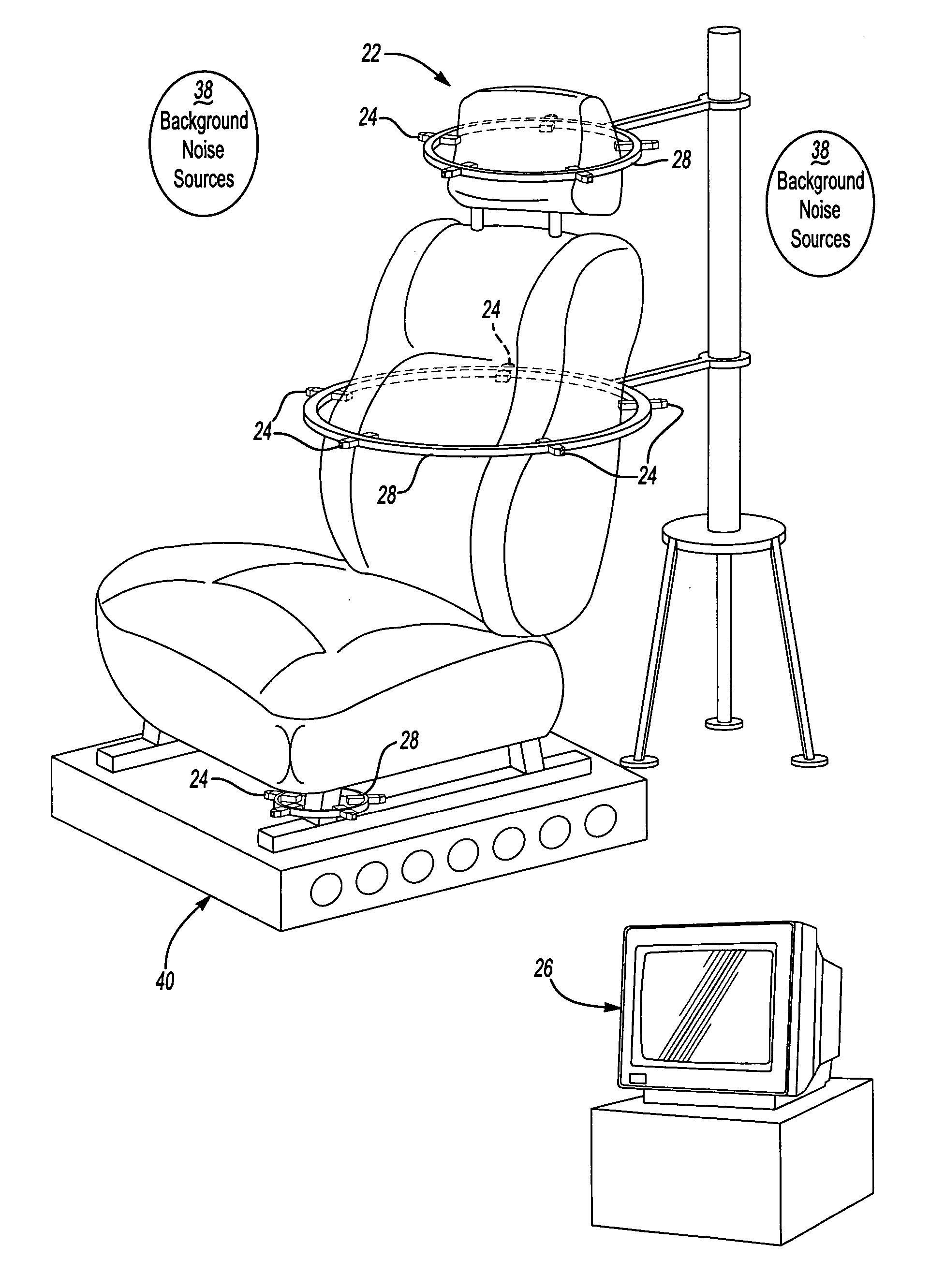
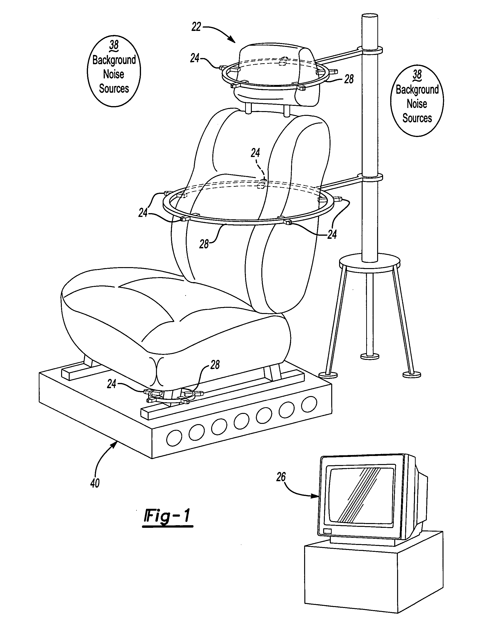
[0018] A first example of a noise diagnostic system 20 according of the present invention is shown in FIG. 1 taking measurements from a noise source 22, in this case a vehicle seat. The system 20 generally comprises a plurality of transducers 24, such as microphones, connected to a computer 26 (connections not shown). The computer 26 may include additional hardware such as a signal analyzer or a digital sound processing computer board (not shown). As is well-known, the computer 26 includes a processor operating a computer programs stored on computer storage media, which may be one or more of RAM, ROM, hard-drive, CD-ROM, DVD, optical, electronic or magnetic media, or any other computer-readable medium. Computer media stores a computer program, which when executed by processor performs the steps described below, including performance of the algorithms of the present invention described below.

[0019] In FIG. 1, each of the transducers 24 are mounted to a ring 28 that surrounds a porti...


PUM


Abstract

A system extracts the sound spectrum and sound pressure level (SPL) values of a target source in a non-ideal environment. This system can be critical for in-line or end-of-line quality control (QC) testing of sound-producing products in a manufacturing environment in which background noise level is high. The underlying principle of this system is the assumption that the sound field can be described using two sets of expansion functions, one for direct sound radiation from a target source and the other for the background sounds that travel in the opposite direction as that of direct sound from the target. The coefficients associated with these expansion functions are determined in a similar manner as those in the Helmholtz Equation Least Squares (HELS) method. Once the expansion coefficients are determined, however, only the direct sound spectrum and corresponding SPL value are displayed. This allows for suppression of background noise produced by the neighboring sources and reflections from nearby surfaces.

Description

[0001] This application claims priority to U.S. Provisional Application Ser. No. 60 / 698,406, filed Jul. 12, 2005.BACKGROUND OF INVENTION [0002] This invention provides a method and system for rapid diagnosis of the sound spectrum and sound pressure level (SPL) values of a target source in a non-ideal environment with improved speed and efficiency. Because of its speed and efficiency even in noisy environments, the invention is useful for in-line or end-of-line quality control (QC) testing of sound-producing products in a general manufacturing environment. [0003] Currently, QC testing is conducted inside a quiet chamber that is separated from an assembly line or inside an enclosure designed and installed on a particular assembly line. The downsides of these approaches are that: 1) QC process becomes costly because of the costs involved in building the chamber or enclosure; 2) QC testing is time consuming because the product must be transported to and from the chamber; 3) testing effi...

Claims


Application Information

Patent Timeline
Patent Type & Authority Applications(United States)
IPC IPC(8): H04B15/00
CPCG01H3/125
Inventor WU, SEAN F.
Owner WAYNE STATE UNIV
Why Eureka
Try Eureka