Method of determining at least one variable of a WDM optical network

Active Publication Date: 2007-02-01
CIENA
View PDF3 Cites 6 Cited by
  • Summary
  • Abstract
  • Description
  • Claims
  • Application Information

AI Technical Summary

Benefits of technology

[0009] Yet another object of the invention is to provide a method of placement of various optical componen

Problems solved by technology

The more sophisticated and advanced the technology, the greater the capability and functionality of the nodes, but generally at the expense of increased co

Method used


Image

  • Method of determining at least one variable of a WDM optical network
  • Method of determining at least one variable of a WDM optical network
  • Method of determining at least one variable of a WDM optical network

Examples


Example

[0018] The preferred forms of the invention will now be described with reference to FIGS. 1, 2, 3A and 3B. The appended claims are not limited to the preferred forms and no term and / or phrase used herein is to be given a meaning other than its ordinary meaning unless expressly stated otherwise.

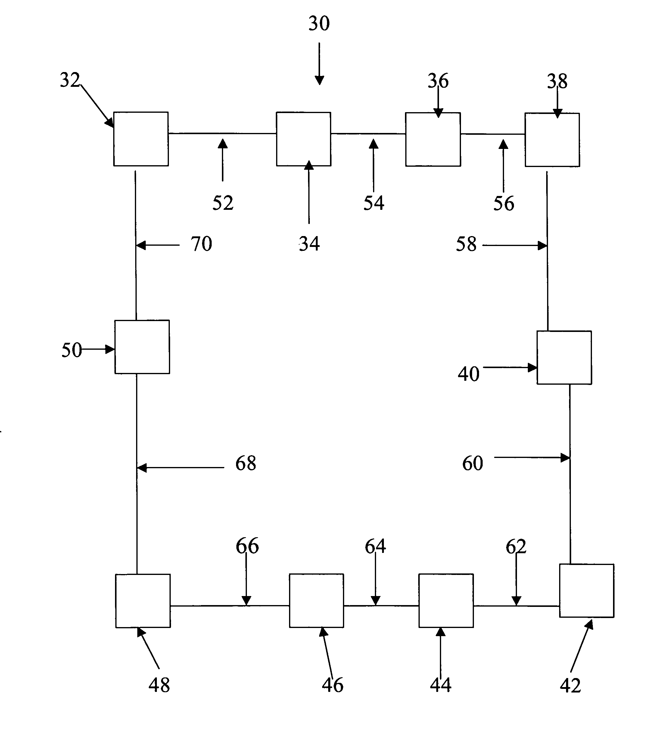
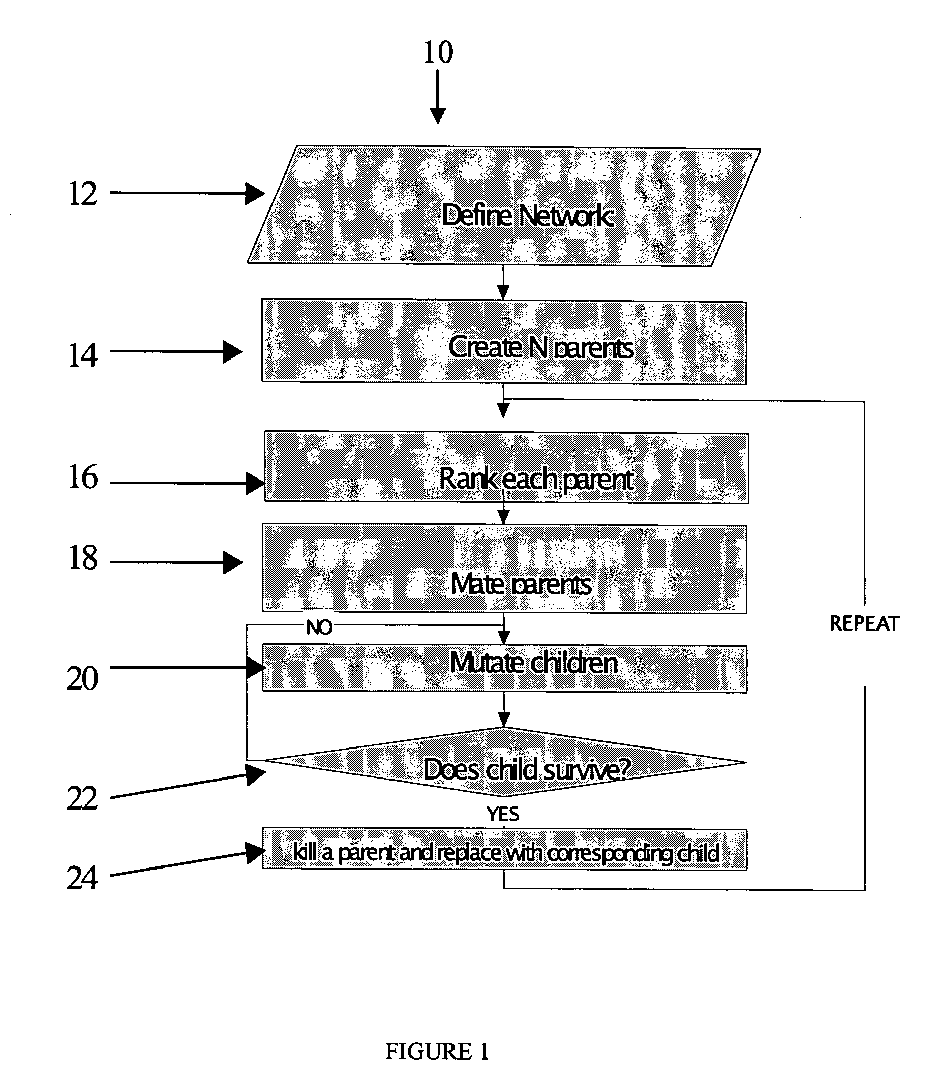
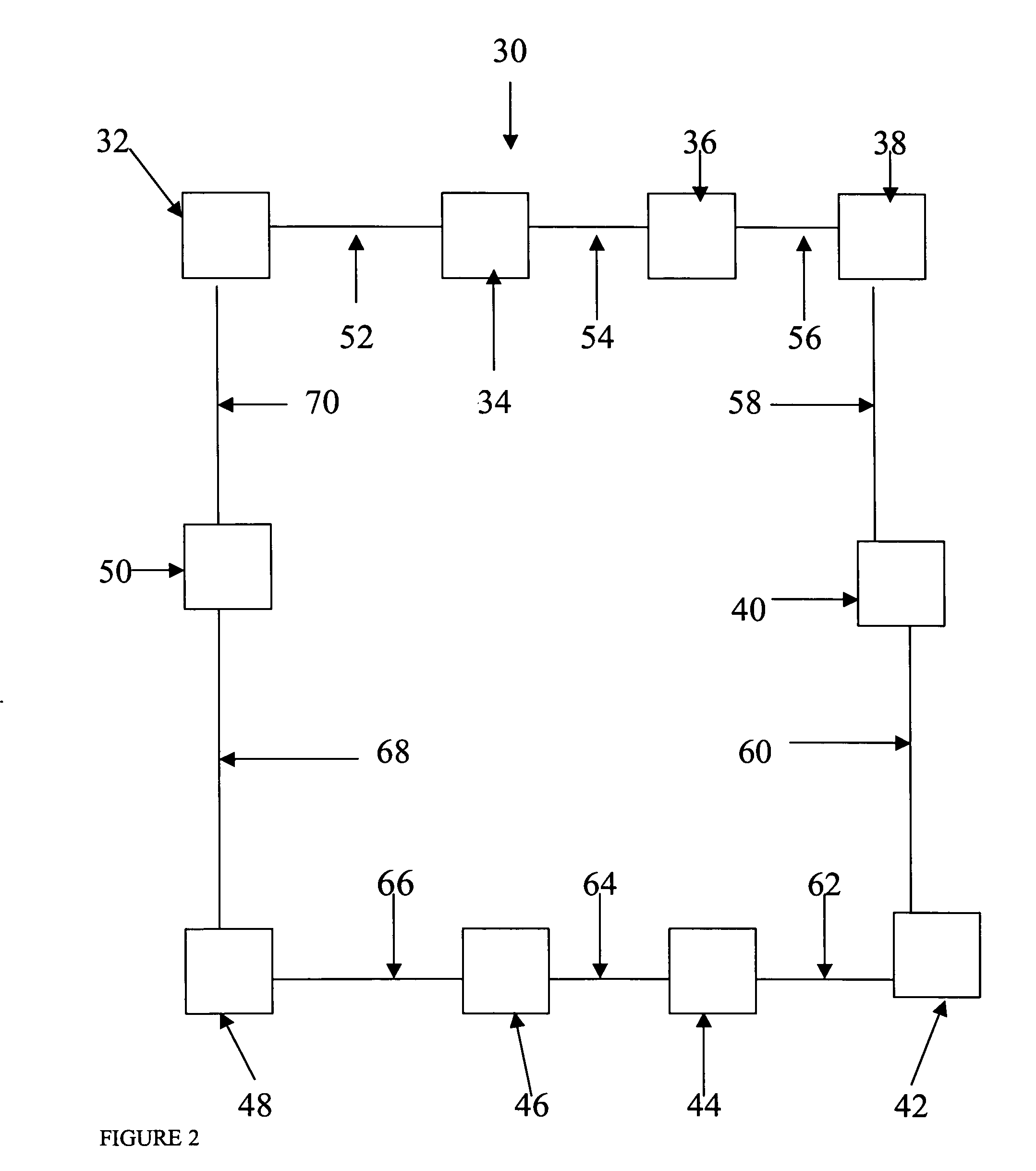
[0019]FIGS. 1, 3A and 3B illustrate a preferred method 10 including steps 12 through 24 for optimizing a WDM optical ring network 30 illustrated in FIG. 2. The WDM optical network 30 includes ten (10) nodes identified by reference numerals 32, 34, 36, 38, 40, 42, 44, 46, 48 and 50. Each pair of adjacent nodes defines a path. For example, a path 52 exists between nodes 32 and 34. Each corresponding pair of nodes 34 and 36, 36 and 38, 38 and 40, 40 and 42, 42 and 44, 44 and 46, 46 and 48, 48 and 50, and 50 and 32 define paths 54, 56, 58, 60, 62, 64, 66, 68 and 70, respectively.

[0020] Each of the paths 52 through 70 in the WDM optical network 30 has a baseline demand. In order to keep the deman...


PUM


Abstract

A method of optimizing a WDM optical ring network configuration using a genetic algorithm. Preferably, the method includes the steps of initially defining one or more parameters for a WDM optical network or portion of a WDM optical network and creating a plurality of parents each having a gene structure corresponding to the one or more parameters of the WDM optical network or portion thereof. The parents are then ranked according to predetermined fitness criteria. The highest ranking parents are then mated to form one or more children. Preferably, the children are then optionally mutated before or after testing to ensure that they satisfy predetermined network demands. Suitable children replace lower ranking parents to form new parents. The process is then repeated by mating the highest ranking parent in an effort to further optimize the network. Various steps in the genetic algorithm can be repeated until an optimal design is achieved.

Description

FIELD OF THE INVENTION [0001] A preferred form of the present invention is directed to a method of determining at least one variable of a WDM optical network. More particularly, the present invention is directed to a method that utilizes a genetic algorithm to determine one of more variables in a WDM optical network to create a robust and cost-effective WDM optical network. The variables include but are not limited to the placement of components (e.g., filters, regenerators, wavelength converters, etc.) in the WDM optical network. BACKGROUND OF THE INVENTION [0002] Various optical networks have been previously proposed for transmitting information including but not limited to audio, video and data from one location to another. Originally, the fiber optic industry used single wavelength transmission links. Multiplexing based on wavelength has been utilized more and more in optical networks to greatly increase transmission capacity over single wavelength transmission links. Specifical...

Claims


Application Information

Patent Timeline
IPC IPC(8): H04B10/08
CPCH04J14/0227H04J14/0283H04J14/0241H04L41/16H04L41/145
Inventor FRANKEL, MICHAEL Y.
Owner CIENA
Why Eureka
Try Eureka