Method and apparatus for receiving data

a technology for receiving data and receiving devices, applied in electrical devices, electromagnetic transmission, transmission monitoring/testing/fault measurement systems, etc., can solve problems such as difficult receiving operation, and achieve the effect of increasing transmission rate and high sensitive receiving level

Inactive Publication Date:
View PDF5 Cites 53 Cited by
  • Summary
  • Abstract
  • Description
  • Claims
  • Application Information

AI Technical Summary

Benefits of technology

[0010] A synchronous detection system brings a highly sensitive receiving level. When a synchronous detection system is r...

Problems solved by technology

On the other hand, in a PSK system, the configuration of a transmitter can be simpl...

Method used


Image

  • Method and apparatus for receiving data
  • Method and apparatus for receiving data
  • Method and apparatus for receiving data

Examples


Embodiment Construction

[0019] Explanatory embodiments of the invention are explained below in detail with reference to the drawings.

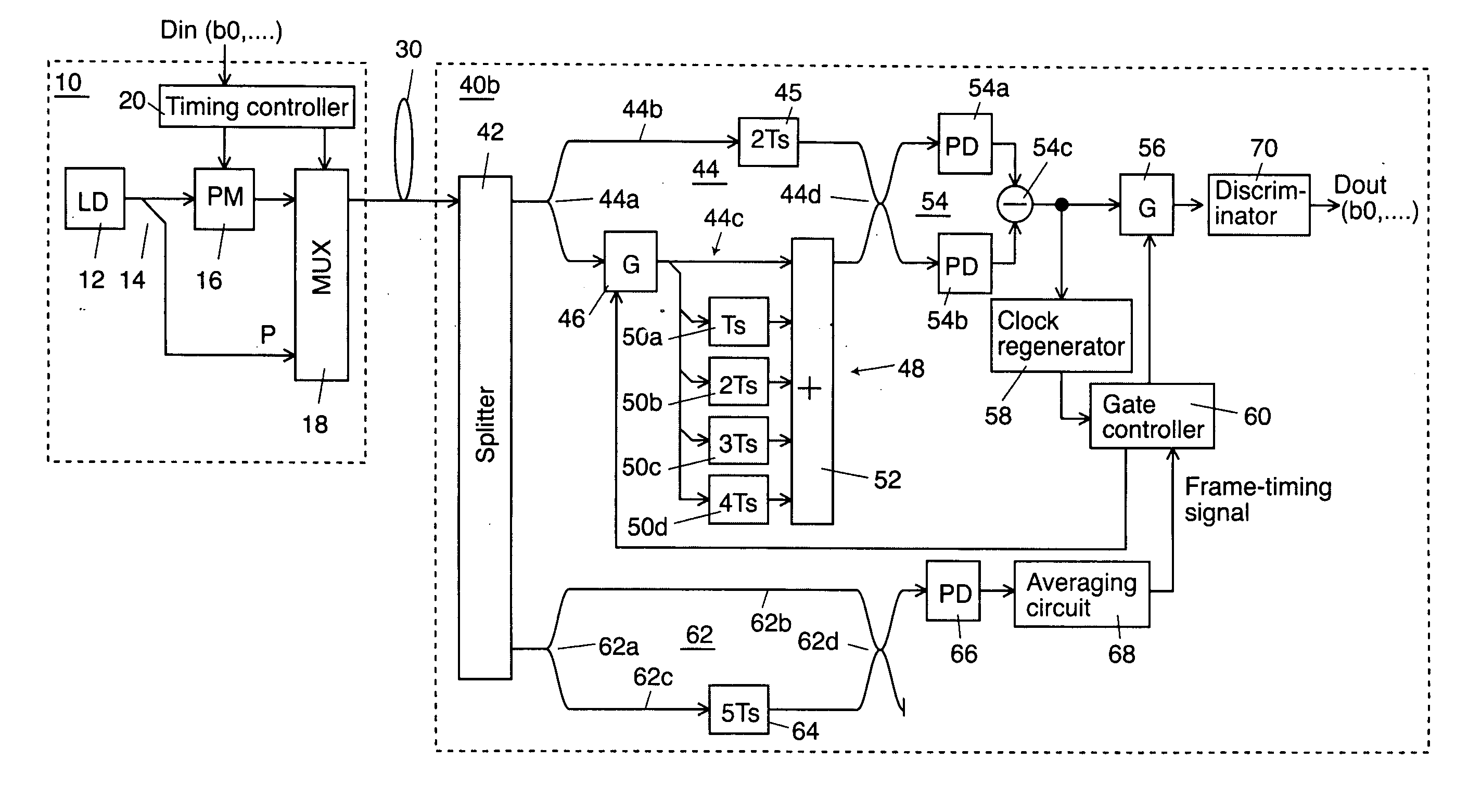
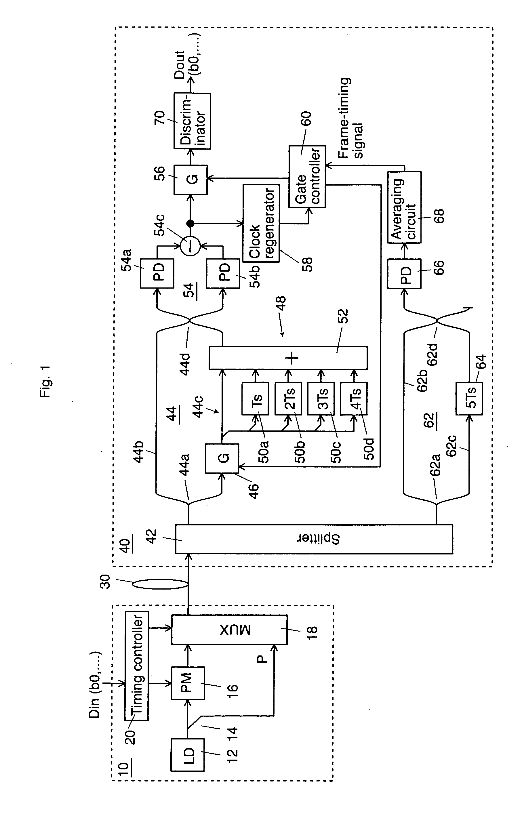
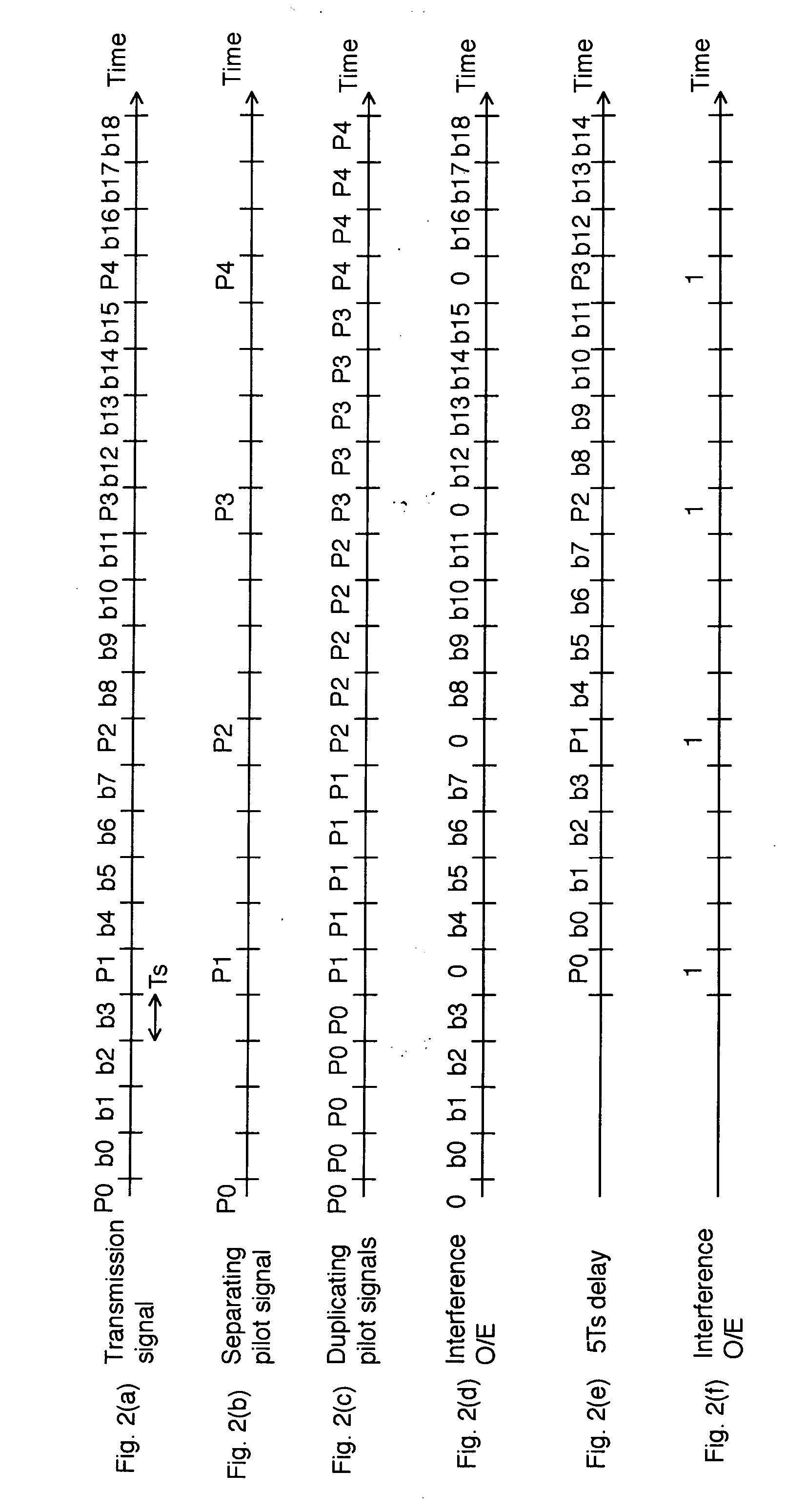
[0020]FIG. 1 shows a schematic block diagram according to a first exemplary embodiment of the invention which is applied to an optical transmission system using BPSK (Binary Phase Shift Keying) modulation and FIG. 2 shows a timing chart of the embodiment. In the optical domain of this embodiment, a binary digit “0” is expressed as a relative optical phase “0”, a binary digit “1” is expressed as a relative optical phase “π”, and a pilot signal being inserted in or time-division-demultiplexed with a data light is expressed as a relative optical phase “0”.

[0021] A laser diode 12 in an optical transmitter 10 generates a coherent continuous laser light to be a carrier. An optical splitter 14 splits the output laser light from the laser diode 12 into two portions and applies one split light to a phase modulator 16 and the other to a multiplexer 18 as a pilot signal.

[0022] A timi...


PUM


Abstract

An optical transmitter generates a transmission signal having a frame as a unit, the frame including a single optical pilot signal with a constant optical phase and a plurality of phase-modulated optical data signals, and outputs the transmission signal into a transmission line. In a receiver, a splitter splits the optical signal input from the transmission line. On a second arm of a Mach-Zehnder interferometer, an optical gate transmits the optical pilot signal and a duplicator duplicates the optical pilot signal output from the optical gate at predetermined time intervals. A balanced optical receiver converts the interfered optical signal output from the interferometer into an electrical signal. A gate and a discriminator extract the data from the electrical signal output from the receiver.

Description

CROSS REFERENCE TO RELATED APPLICATIONS [0001] This application claims priority to Japanese Patent Application No. 2005-196954, filed on Jul. 6, 2005, the entire contents of which are incorporated herein by reference. FIELD OF THE INVENTION [0002] This invention relates to method and apparatus for receiving data. BACKGROUND OF THE INVENTION [0003] In the optical fiber transmission, it is inevitable to have the influence such as polarization mode dispersion and chromatic dispersion from an optical fiber transmission line so that the signal quality is deteriorated and the receiving sensitivity is decreased. [0004] A number of receiving systems have been proposed according to the types of modulation systems. For instance, a heterodyne detection system based on a reference carrier is described in “Degradation of Bit-Error Rate in Coherent Optical Communications Due to Spectral Spread of the Transmitter and the Local Oscillator, ” IEEE / USAJ. Lightwave Technol., Vol. LT-2, pp. 1024-1033, ...

Claims


Application Information

Patent Timeline
IPC IPC(8): H04B10/12H04B10/00H04B10/516H04B10/07H04B10/548H04B10/58H04B10/61
CPCH04B10/677H04L7/0075H04B10/69
Inventor KAMIO, YUKIYOSHIMIYAZAKI, TETSUYA
Why Eureka
Try Eureka