Core for turbomachine blades

a turbomachine blade and core technology, applied in the field of turbomachine blades, can solve the problems of long operation and high cost, and achieve the effect of precise positioning of the assembled core elements

Active Publication Date: 2007-02-01
SN DETUDE & DE CONSTR DE MOTEURS DAVIATION S N E C M A
View PDF6 Cites 20 Cited by
  • Summary
  • Abstract
  • Description
  • Claims
  • Application Information

AI Technical Summary

Benefits of technology

[0013] This therefore allows relatively precise positioning of the assembled core elements, which is reproducible in an industrial process. Preferably, these rods also define orifices for extraction of the cooling fluid through the squealer.

Problems solved by technology

This operation is lengthy and expensive.

Method used


Image

  • Core for turbomachine blades
  • Core for turbomachine blades
  • Core for turbomachine blades

Examples


Embodiment Construction

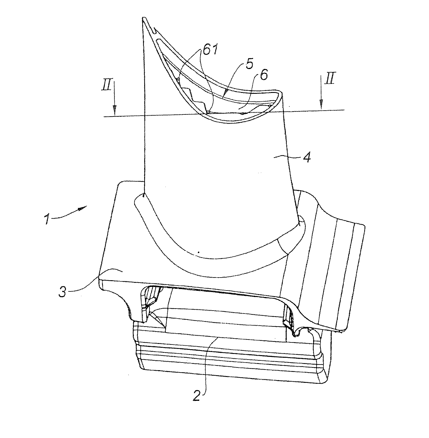
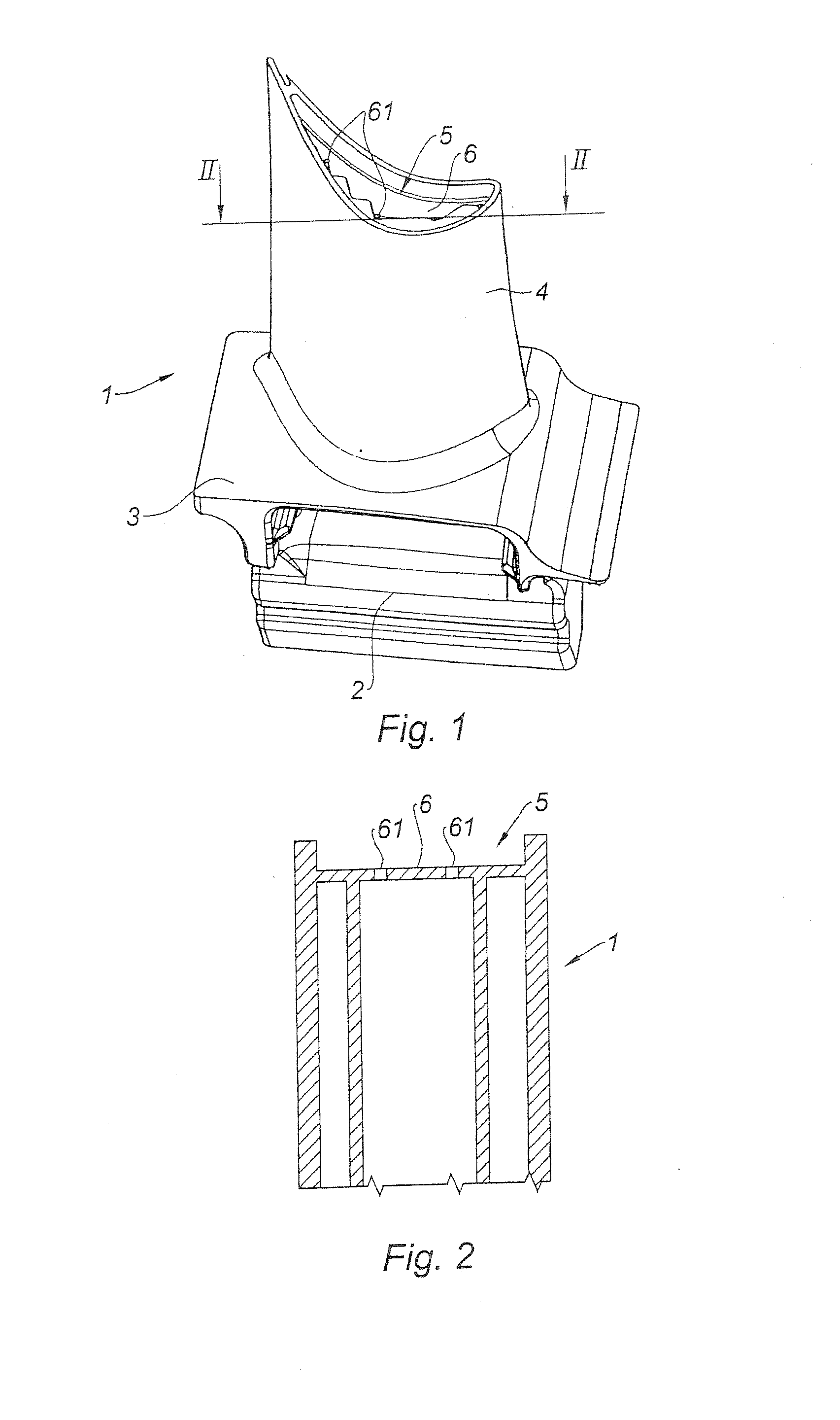
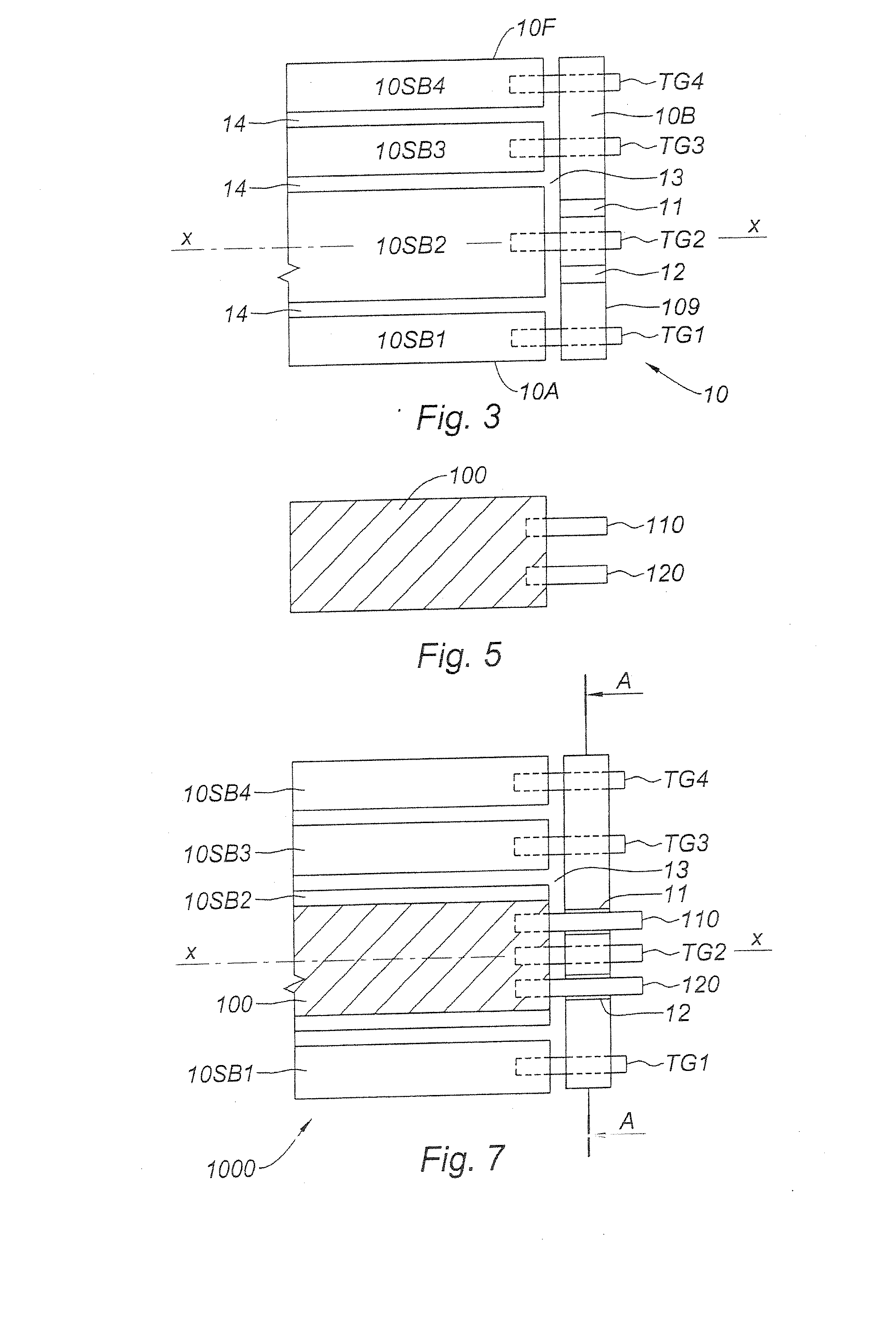
[0032]FIG. 3 shows, along the main axis XX of the blade, a portion of a main core which corresponds to the upper portion of the airfoil, the tip being to the right in the figure. The rest of the core corresponding to the portion of the blade with the root and the platform is not visible. This main core is, for example, the core on the pressure-face side of a multiple core. A multiple core allows hollow blades to be produced with multiple cavities separated by partitions, a cooling fluid circulating in said cavities. This cooling fluid may be air taken from the compressor, especially in a gas turbine engine. FIG. 4 shows an example of the overall profile of this main core.

[0033] This main core 10 here consists of a plurality of elements, separated from one another by spaces, constituting the walls of the cooling cavities after the metal has been cast. The schematic drawing of FIG. 3 shows an anterior edge 10A on the leading-edge side of the airfoil, a rear edge on the trailing-edge ...


PUM


Abstract

The present invention relates to a ceramic core used in the manufacture, by lost wax casting, of a turbomachine blade with cooling cavities and a squealer, comprising at least one main core, wherein the main core (10) comprises an element (10B) shaped so as to constitute the squealer and an element (10SB) shaped so as to constitute at least one cavity beneath the squealer, the two elements leaving between them a space (13) shaped so as to constitute, at least in part, the bottom wall of the squealer. In particular, the elements (10B and 10SB) are joined together by ceramic rods (TG).

Description

FIELD OF THE INVENTION [0001] The present invention relates to the field of turbomachine blades, especially to that of blades obtained by casting a molten alloy in a mold using the technique of lost wax casting. PRIOR ART [0002] The search for enhanced performance levels in engines involves in particular more effective cooling of the turbine blades located immediately downstream of the combustion chamber. This requirement means that more elaborate internal cavities have to be formed inside these blades for the circulation of the cooling fluid. These blades have the particular feature of having several metal walls and therefore require the manufacture of increasingly complex ceramic cores. [0003] The technique of manufacturing blades of this type therefore includes a first step of forming the core. The core is made of a ceramic with a generally porous structure and is produced from a mixture consisting of a refractory filler in the form of particles and a relatively complex organic f...

Claims


Application Information

Patent Timeline
Patent Type & Authority Applications(United States)
IPC IPC(8): F01D5/18
CPCB22C9/103B22C21/14B22C9/108
Inventor GUERCHE, DIDIERHANNY, JEAN-CLAUDEPRIGENT, SERGE
Owner SN DETUDE & DE CONSTR DE MOTEURS DAVIATION S N E C M A
Why Eureka
Try Eureka