Mobile communication system, radio base station and radio mobile station

a mobile communication system and radio base station technology, applied in the field of mobile communication system, can solve the problems of wasting processing at this base station, the decline in the reception quality of other mobile stations at this other base station, etc., and achieve the effect of improving system performance, reducing the amount of interference impressed upon other radio base stations, and improving system performan

Inactive Publication Date: 2007-02-01
FUJITSU LTD
View PDF14 Cites 26 Cited by
  • Summary
  • Abstract
  • Description
  • Claims
  • Application Information

AI Technical Summary

Benefits of technology

[0014] Another object of the present invention is to make it possible to obtain a diversity effect in accordance with conditions at the time of handover, or to reduce the amount of interference imposed on other communications at the time of handover, thereby improving the performance of the system (suppressing a decline in reception quality and improving transmission capacity).
[0032] Further, in accordance with the mobile station of the present invention, the mobile station measures radio environments between this itself and one or more radio base stations, compares, for each radio base station, a radio environment measurement value with a first threshold value and a second threshold value that is smaller than the first threshold value, determines that the radio environment is one in which a transmission to the radio base station is possible if the measurement value is greater than the first threshold value, determines that the radio environment is one in which a transmission to the radio base station is impossible if the measurement value is less than the first threshold value and greater than the second threshold value, determines that the radio environment is one in which no interference will be impressed upon the radio base station, even if the mobile station transmits, if the measurement value is less than the second threshold value, and performs a transmission of uplink data if the radio environments between this mobile station and one or more radio base stations are radio environments in which the transmission is possible and, moreover, the radio environment between this mobile station and any radio base station is not a radio environment in which the transmission is impossible. As a result, the effect of diversity can be obtained, or amount of interference impressed upon communication with other base stations can be reduced, in accordance with the radio environments between the mobile station and plurality of radio base stations, and the performance of the system can be improved. In this case, if the first and second threshold values are controlled depending upon the type of data transmitted, the optimum threshold values can be set based upon the urgency of the data, the quality required by the data, etc.

Problems solved by technology

This is a method that allows the existence of a certain amount of interference at all times. As a consequence, the amount of interference imposed upon another base station at handover increases and there is a decline in the reception quality from other mobile stations at this other base station.
In this case the probability that the base station constituting the non-serving cell will receive the signal correctly diminishes, the processing executed at this base station is wasted and radio waves from the above-mentioned mobile station will interfere with signal radio waves between the base station and other mobile stations.

Method used


Image

  • Mobile communication system, radio base station and radio mobile station
  • Mobile communication system, radio base station and radio mobile station
  • Mobile communication system, radio base station and radio mobile station

Examples


first embodiment

(B) First Embodiment

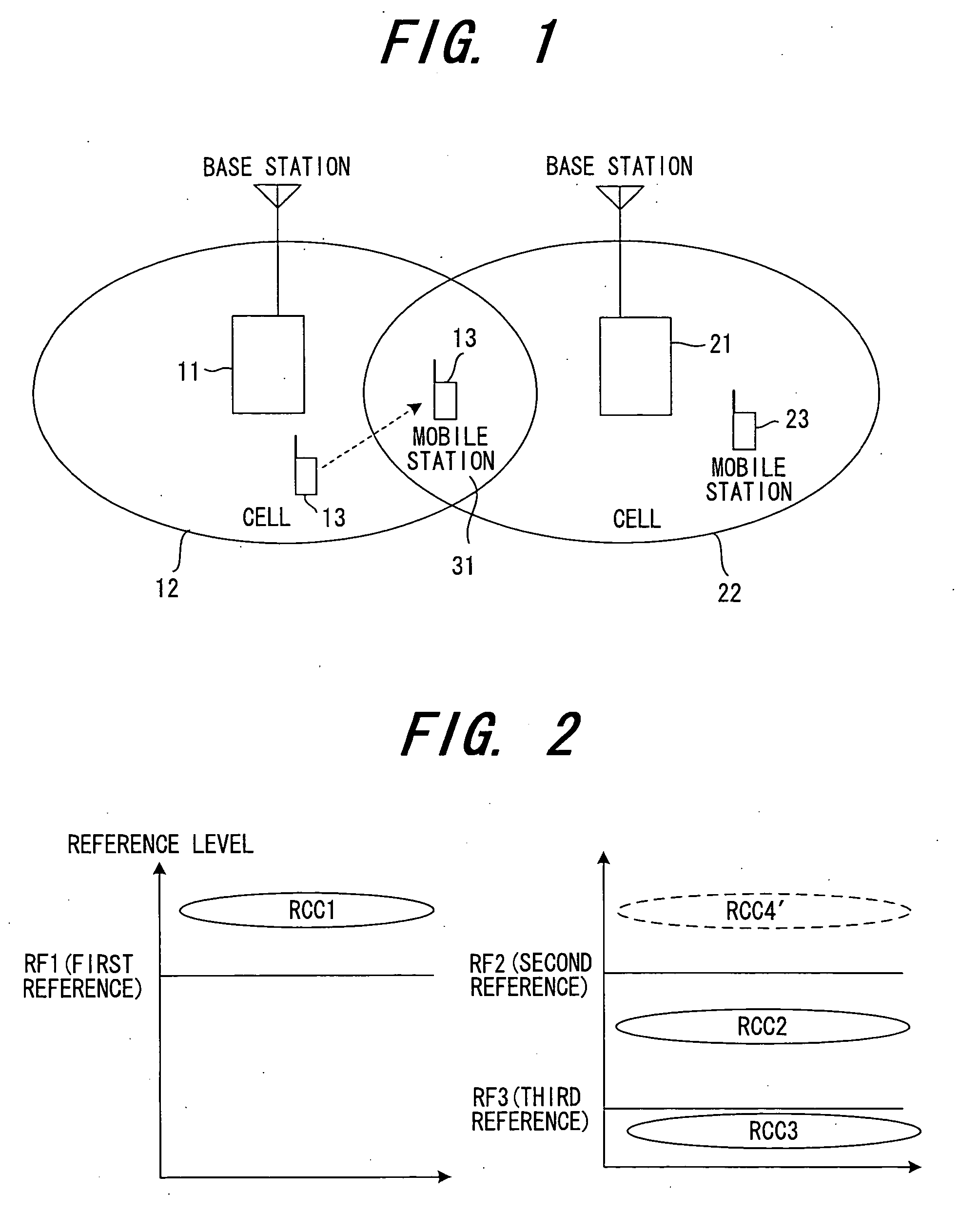
[0071] As shown in FIG. 1, it is assumed that the mobile station 13 is present at a location that is equidistant from the first radio base station 11 and second radio base station 21. In such case the reception levels of a signal from the mobile station 13 at the first radio base station 11 and at the second radio base station 21 will be the same in average terms and the signal from the mobile station 13 will be capable of being received by both the first radio base station 11 and second radio base station 21. In actuality, however, the reception levels fluctuate independently owing to fading and the like and, as a consequence, whether the signal from the mobile station 13 can be received correctly at each of the radio base stations 11, 21 fluctuates independently.

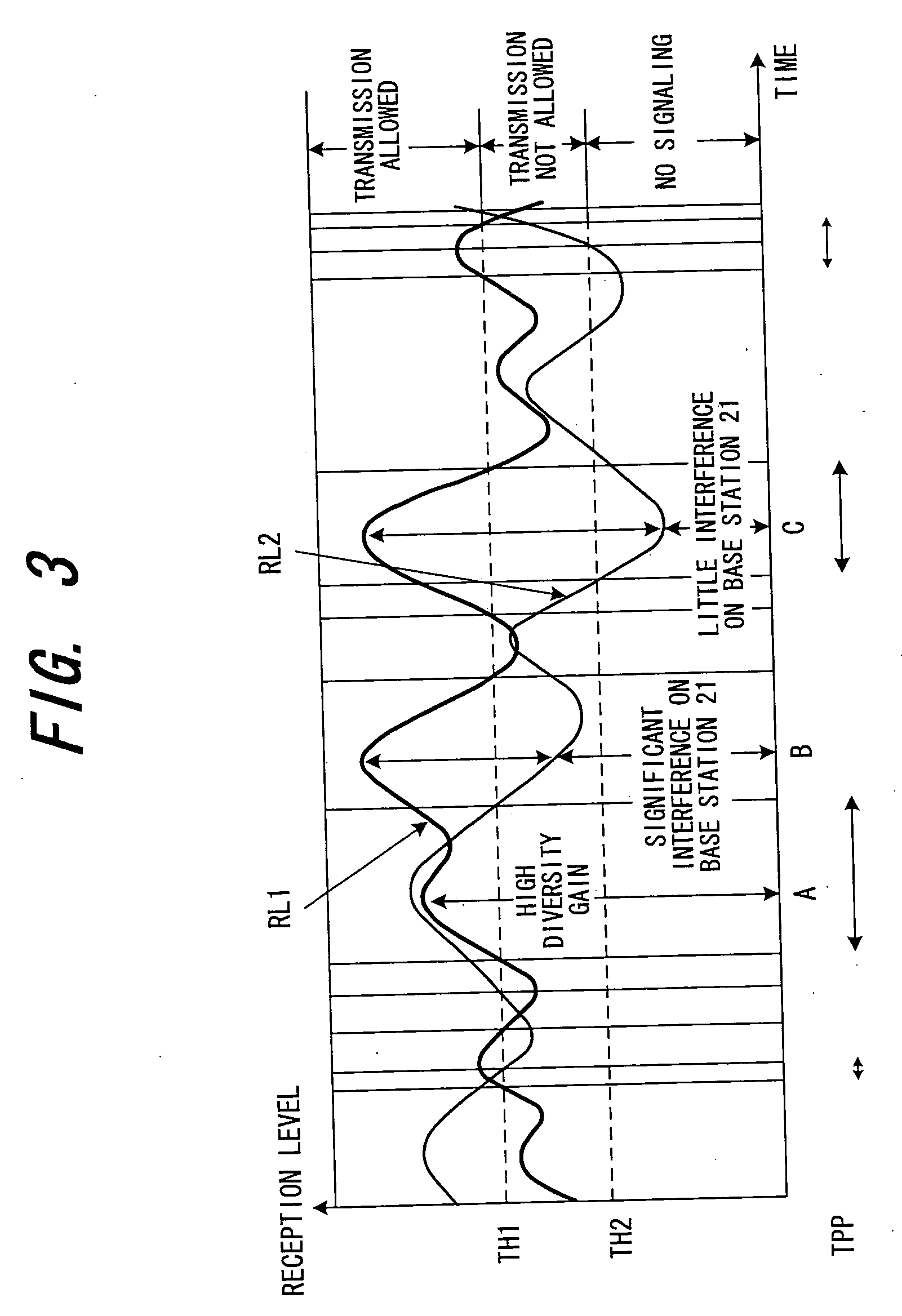
[0072]FIG. 3 is a diagram useful in describing ranges of levels for allowing or not allowing transmission. At a time A in FIG. 3, reception levels RL1, RL2 of a signal from the mobile station 13 are gr...

second embodiment

(C) Second Embodiment

[0108] In the first embodiment, the first and second threshold values TH1 and TH2 are fixed. In the second embodiment, however, these threshold values can be varied depending upon the QoS (Quality of Service) or real-time property of the data transmitted. For example, in the case of a circuit-switching-type service such as a voice call or TV telephone call, real-time communication is required. Therefore, in comparison with the case of a packet call (e-mail, etc.) in which there is little demand for real-time communication, the threshold value TH1 is reduced and the threshold value TH2 enlarged so as to raise the probability that transmission will be allowed. In other words, the range of reception levels over which transmission is not allowed is narrowed.

[0109]FIG. 10 is a diagram useful in describing ranges of levels at a base station for allowing or not allowing transmission in a case where the first threshold value TH1 is made small and the second threshold v...

third embodiment

(D) Third Embodiment

[0112] The first and second embodiments relate to a case where the reception level of the pilot signal included in the DPCCH is measured. In a third embodiment, however, the reception level is measured using a reservation packet.

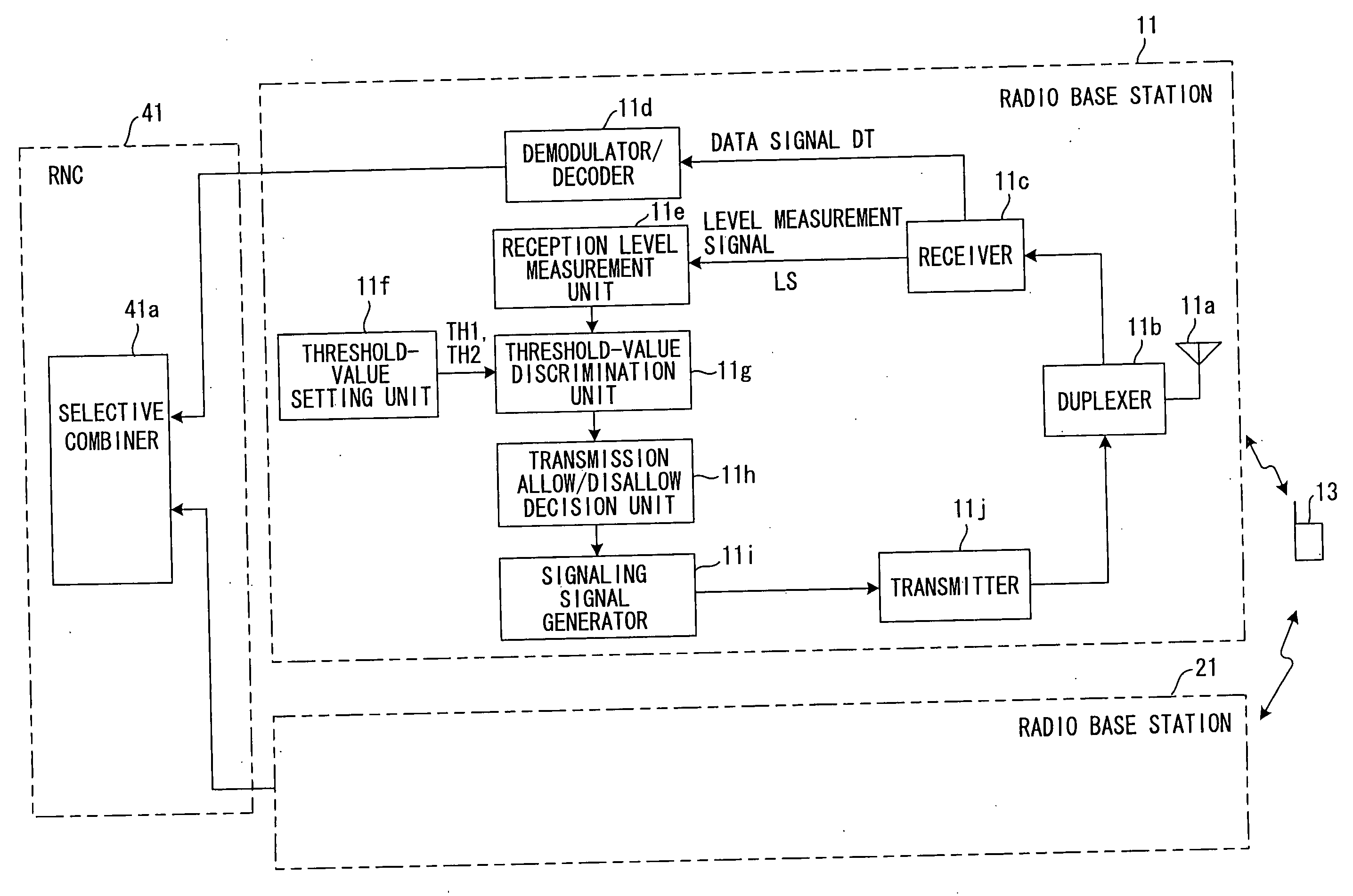
[0113] There are communication systems in which a reservation packet is transmitted from a mobile station to a radio base station and transmission of packet data is started when transmission is allowed by the radio base station. In such a communication system, the reception level can be measured using the reservation packet. In the third embodiment, the radio base stations 11, 21 (see FIG. 1) receive a reservation packet transmitted from the mobile station 13 and, upon measuring the reception level of the reservation packet, transmit a signalling packet that instructs the mobile station that it is allowed or not allowed to transmit.

[0114]FIG. 12 illustrates examples of reservation packets according to the third embodiment, in which (A) ...


PUM


Abstract

Each radio base station (11, 21) evaluates whether a radio environment between itself and a mobile station is an environment in which diversity gain is obtained or an environment in which diversity gain is not obtained and interference will be impressed upon communication with another radio base station, allows the mobile station to transmit if the radio environment is the environment in which diversity gain is obtained, disallows the mobile station to transmit if the environment is the environment in which interference will be impressed upon communication with another radio base station, and neither allows nor disallows the mobile station to transmit if the environment is an environment in which although diversity gain is not obtained, no interference will be impressed upon communication with another radio base station. The mobile station performs a transmission of uplink data if it is being allowed to transmit by one or more radio base stations and, moreover, it is not being disallowed to transmit by any radio base station.

Description

BACKGROUND OF THE INVENTION [0001] This invention relates to a mobile communication system having a mobile station and first and second radio base stations for receiving a radio signal transmitted from the mobile station, and to a radio base station and mobile station in this mobile communication system. More particularly, the invention relates to a mobile communication system in which a diversity effect can be obtained and amount of interference impressed on other base stations reduced at the time of handover, and to a radio base station and mobile station in this system. [0002] A W-CDMA mobile communication system is a wireless communication system in which a channel is shared by multiple users. As shown in FIG. 24, the W-CDMA mobile communication system comprises a core network 1, radio network controllers (RNCs) 2, 3, multiplexers 4, 5, radio base stations (Node B) 61 to 65 and a mobile station (UE: User Equipment) 7. [0003] The core network 1 is a network for performing routing...

Claims


Application Information

Patent Timeline
Patent Type & Authority Applications(United States)
IPC IPC(8): H04Q7/20H04B1/707H04J1/00H04W16/28H04W28/00H04W36/18H04W36/36
CPCH04W36/02H04W72/1226H04W72/082H04W36/18H04W72/541H04W72/54
Inventor YANO, TETSUYAMIYAZAKI, SHUNJIOBUCHI, KAZUHISA
Owner FUJITSU LTD
Why Eureka
Try Eureka