Spectrum analyzer control in an oscilloscope

a spectrum analyzer and oscilloscope technology, applied in the field of time domain measurement instruments, can solve the problems of inability to achieve more advanced spectrum analyzer features, inability to control the basic parameters of the frequency domain analysis system by hand, and inability to achieve manual control. , the effect of relying on the sight of the user

Inactive Publication Date: 2007-02-01
LECROY
View PDF23 Cites 49 Cited by
  • Summary
  • Abstract
  • Description
  • Claims
  • Application Information

AI Technical Summary

Benefits of technology

[0007] The invention therefore allows for an enhanced set of analysis tools to be applied to a frequency domain analysis system residing in a time domain measurement instrument.

Problems solved by technology

While dedicated Spectrum Analyzers have been available from any number of sources, they can often be expensive, and require a user to buy such a unit in addition to other test equipment.
However, with these drawbacks, Spectrum Analyzers provide a great level of control of viewing the frequency domain signal.
While the resulting signal can be displayed as a frequency domain signal, more advanced Spectrum Analyzer features have traditionally been lacking in such a setup, primarily because the oscilloscope has not been optimized to perform the Spectrum Analyzer functions.
Thus, the user is limited to manual control of the basic parameters of the frequency domain analysis system.
However, such manual control, relying on the sight of a user, is often inaccurate.

Method used


Image

  • Spectrum analyzer control in an oscilloscope
  • Spectrum analyzer control in an oscilloscope
  • Spectrum analyzer control in an oscilloscope

Examples


Embodiment Construction

[0021] The invention will now be described, making reference to the accompanying drawings.

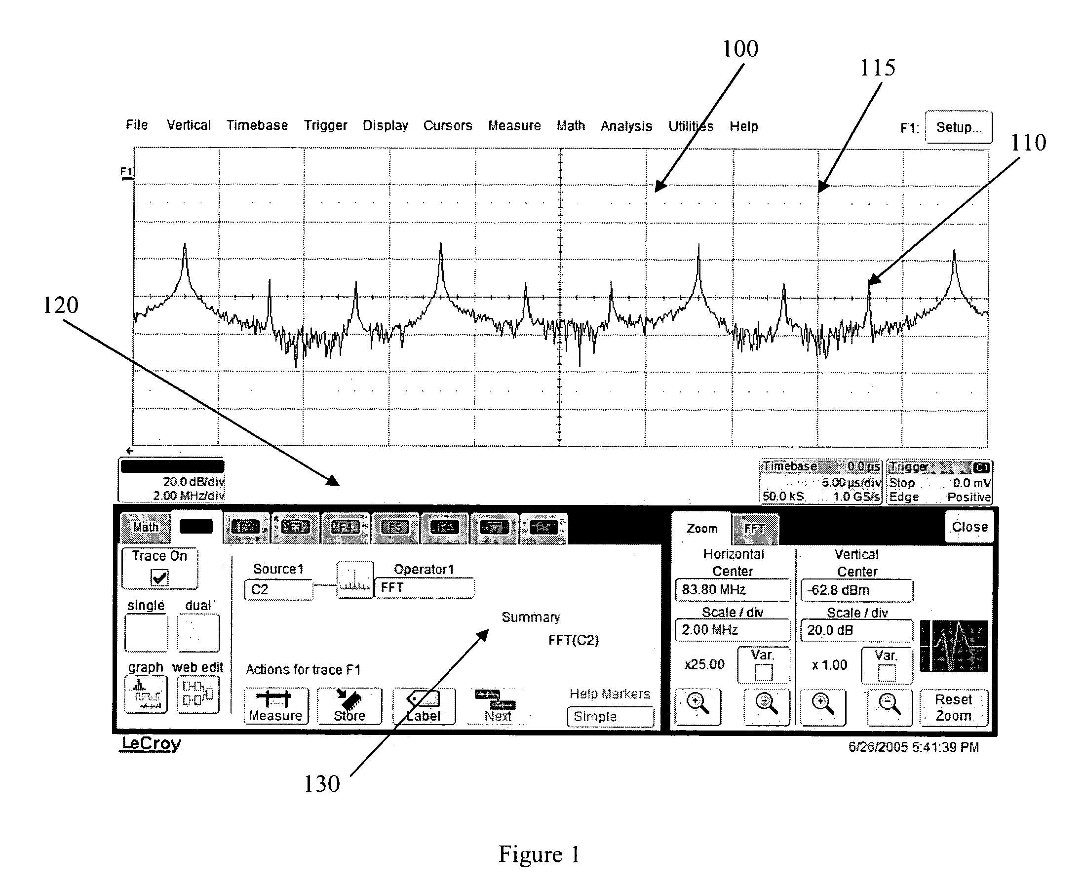
[0022] Referring first to FIG. 1, a display 100 is shown presenting a frequency domain signal 110 in a rendering portion 115 of display 100. Display 100 further comprises a main portion 120 which includes various information and settings regarding the state of the oscilloscope, and the displayed signal. A menu 130 presents various settings that are employed by a user to implement the various features of the current invention. As shown at 130, no parameters are included as the features of the invention have not yet been activated.

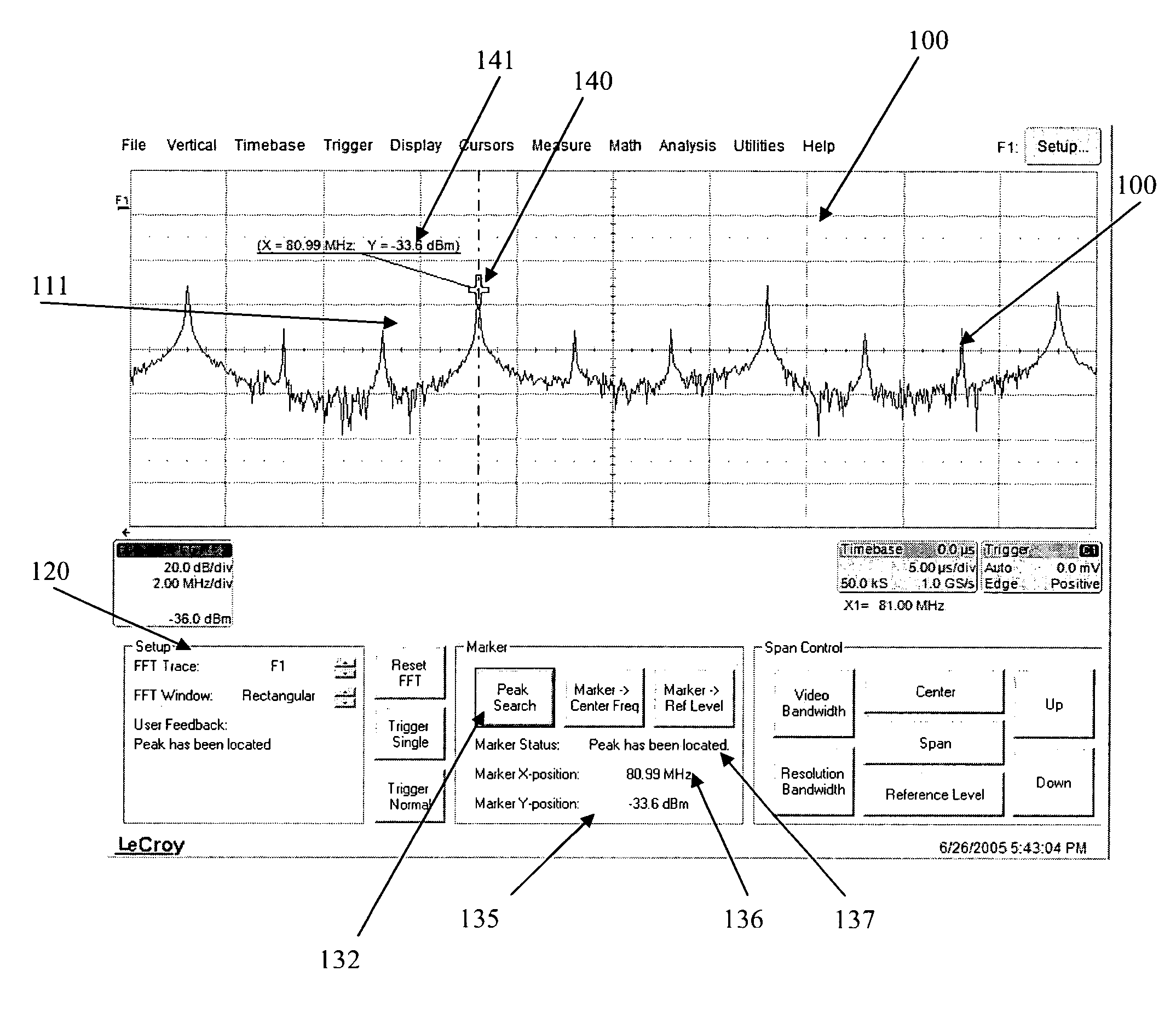
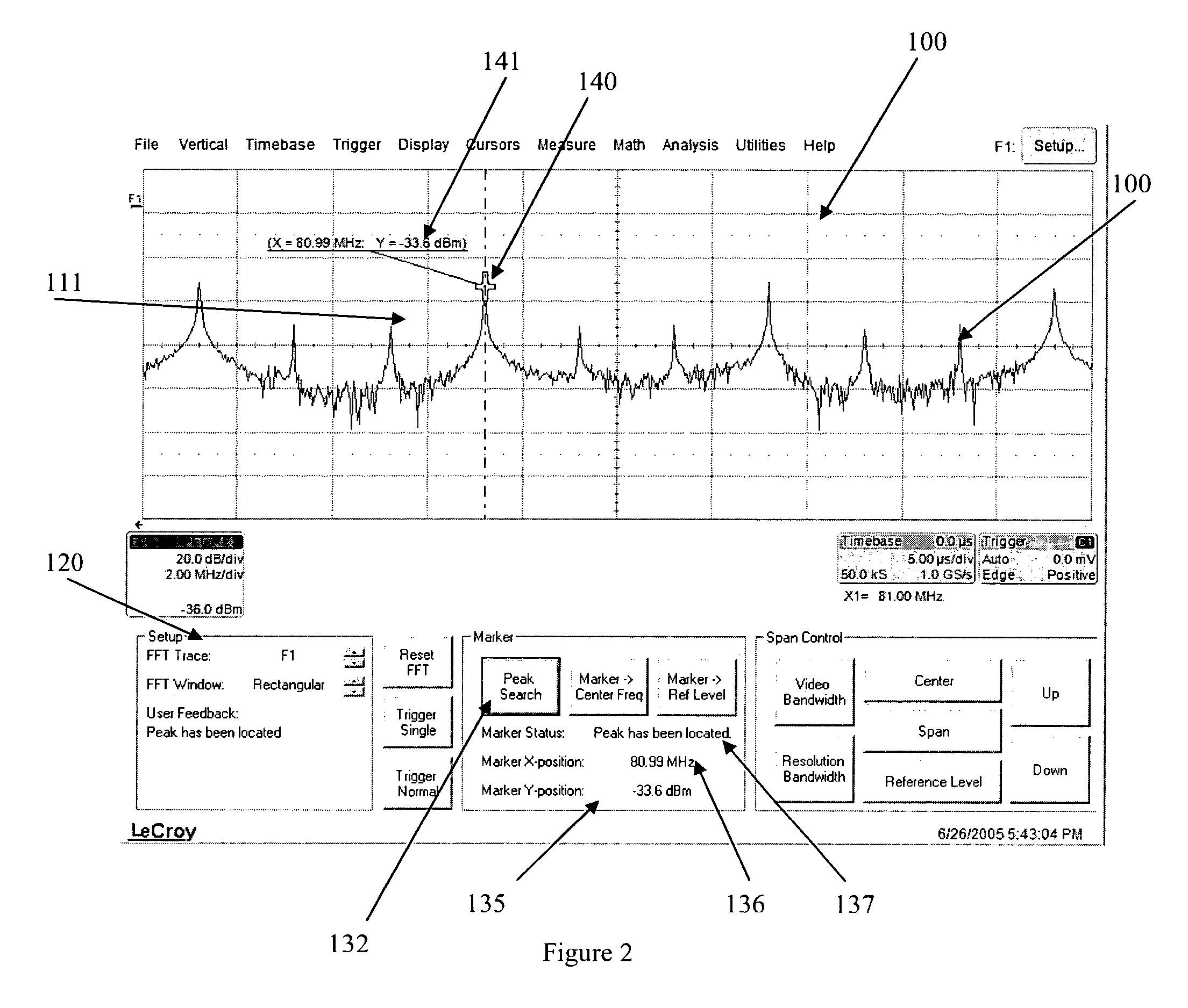
[0023]FIG. 2 depicts display 100 after a peak search function has been employed. In this particular embodiment peak search designation 132 comprises a touch screen, so that the user can implement the feature by touching the screen at the location corresponding to the peak search designation 132. Of course any other type of selection device, such as a mouse pointer or ...


PUM


Abstract

A time domain measurement instrument and method are provided. The instrument comprises an acquisition circuit for acquiring a signal in a time domain and a processor for performing a Fast Fourier Transform (FFT) processing on the acquired signal to generate an FFT of the acquired signal. A frequency domain analysis tool is also provided for analyzing and manipulating the FFT, wherein the frequency domain analysis tool instructs the processor to automatically determine the frequency of a peak amplitude of the FFT, and to determine the amplitude at the determined peak frequency.

Description

BACKGROUND OF THE INVENTION [0001] The present invention relates generally to time domain measurement instruments, such as an oscilloscope, and more particularly to such an instrument that employs a frequency domain analysis feature. [0002] Spectrum analyzers are well known devices that receive an input signal, and sample and display the signal in the frequency domain. While dedicated Spectrum Analyzers have been available from any number of sources, they can often be expensive, and require a user to buy such a unit in addition to other test equipment. However, with these drawbacks, Spectrum Analyzers provide a great level of control of viewing the frequency domain signal. [0003] Oscilloscopes and other time domain analysis measurement instruments are used generally to view an input signal in the time domain. Various functions and measurements may be performed on the time domain displayed signal. Additionally, a number of oscilloscopes allow for the viewing of a signal as if it were...

Claims


Application Information

Patent Timeline
Patent Type & Authority Applications(United States)
IPC IPC(8): G10L19/00
CPCG01R23/16G01R13/029
Inventor HERTZ, MICHAEL G.
Owner LECROY
Why Eureka
Try Eureka