Hybrid vehicle

a hybrid vehicle technology, applied in the direction of battery/fuel cell control arrangement, electric devices, propulsion by batteries/cells, etc., can solve the problem of ineffective utilization of electric power travel modes, and achieve the effect of reliable travel

Inactive Publication Date: 2007-02-08
YAMAHA MOTOR CO LTD
View PDF9 Cites 95 Cited by
  • Summary
  • Abstract
  • Description
  • Claims
  • Application Information

AI Technical Summary

Benefits of technology

[0011] An advantage to this aspect of the present invention is that a reliable travel to the destination is possible in second

Problems solved by technology

Hei 6-245317 only proposes shift to electric power travel mode as a measure for troubl

Method used


Image

  • Hybrid vehicle
  • Hybrid vehicle
  • Hybrid vehicle

Examples


first embodiment

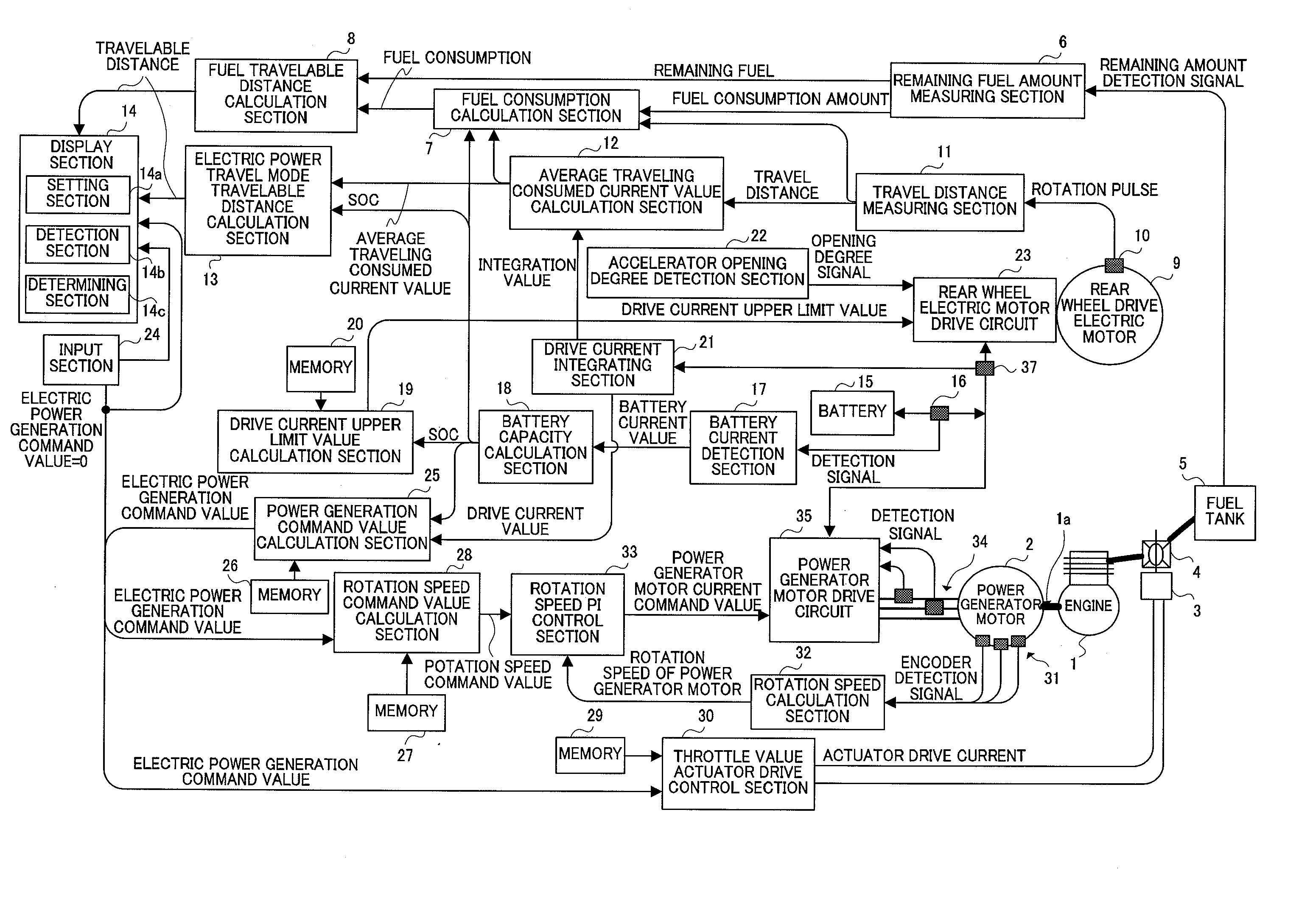
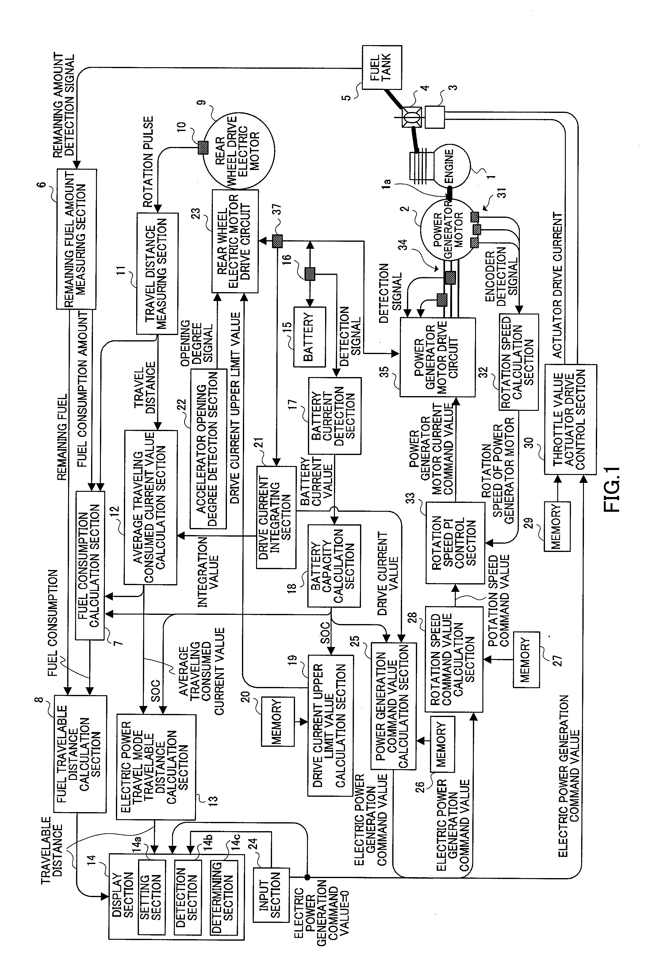
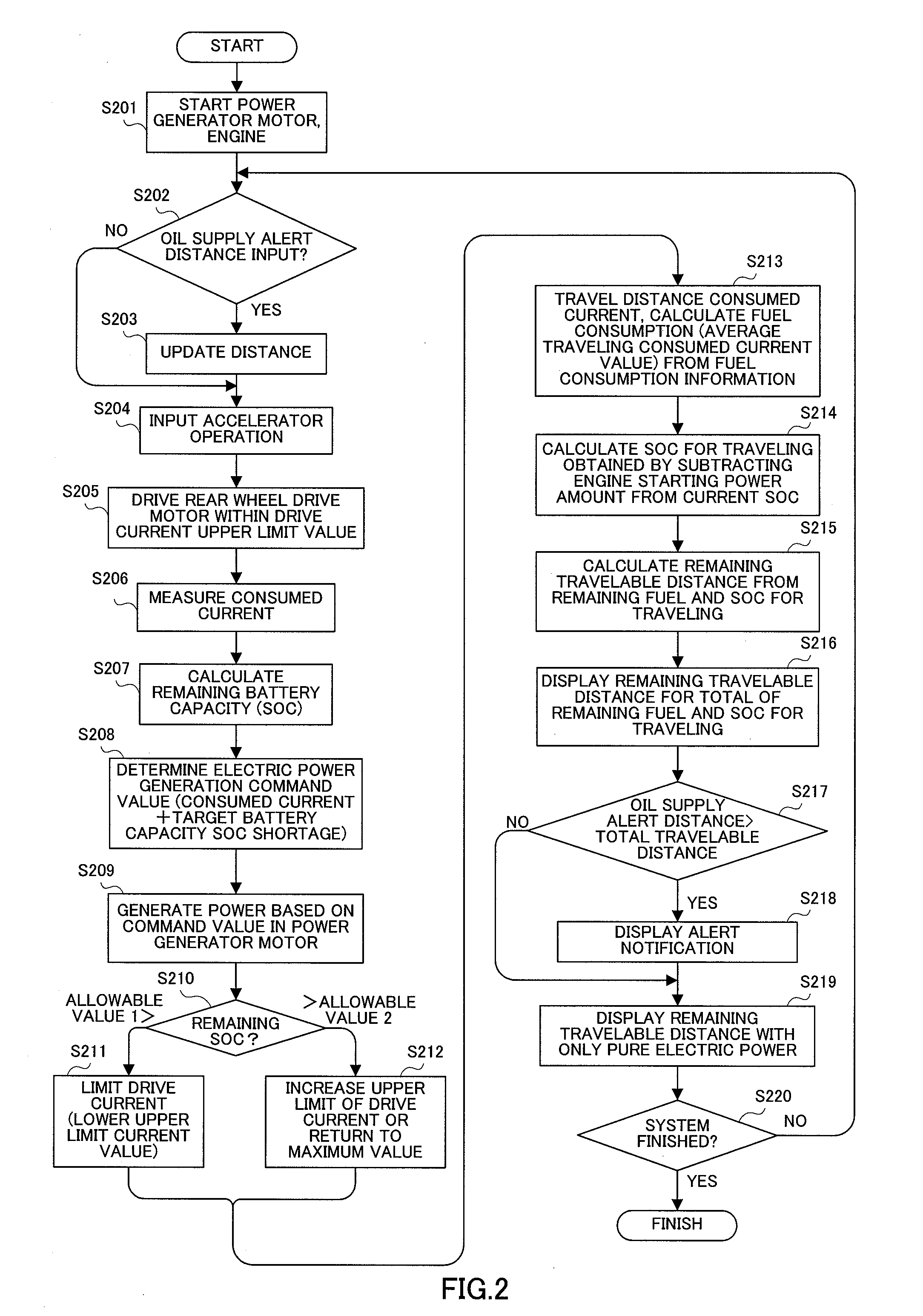
[0019]FIG. 1 to FIG. 3 are diagrams explaining the hybrid vehicle of a FIG. 1 is a block diagram showing a configuration of a control system of the hybrid vehicle; FIG. 2 is a flowchart showing a travel mode shift process; and FIG. 3 is a diagram showing the relationship between the battery charging capacity SOC and allowable values 1 and 2.

[0020] The hybrid vehicle of the present embodiment is a series-type hybrid vehicle including a drive motor for driving drive wheels, a battery for supplying power to the drive motor, and a power generator of engine drive-type capable of charging the battery during traveling. The hybrid vehicle of the present embodiment is configured to drive the power generator motor by the engine and alternatively select between first travel mode of traveling by driving a rear wheel drive electric motor while charging the battery with the power generator motor, and second travel mode of traveling by driving the rear wheel drive electric motor with only accumul...

second embodiment

[0058]FIG. 4 and FIG. 5 are diagrams explaining a hybrid vehicle according to a FIG. 4 is a block diagram showing the configuration of a control system of the hybrid vehicle, and FIG. 5 is a flowchart showing a travel mode shift process.

[0059] The hybrid vehicle of the present embodiment is a series-type hybrid vehicle, similar to the first embodiment. The configuration of the control system of the hybrid vehicle will be explained first with reference to the block diagram of FIG. 4. In the block diagram of FIG. 4, the same components as in FIG. 1 of the first embodiment will be assigned the same reference numerals as in FIG. 1 without further explanations.

[0060] Average traveling consumed current value calculation section 401 calculates the average traveling consumed current value based on the travel distance inputted from travel distance measuring section 11 and the integration value inputted from drive current integrating section 21 and outputs the result to electric power trave...

embodiment 1

[0061] GPS (Global Positioning System) section 403 receives the GPS signal, detects the current position of the hybrid vehicle, and outputs the current position to a electric power travel mode desired travel distance calculation section 405. User destination input apparatus 404 is an input apparatus for the user to input the destination, and the target position corresponding to the input destination is outputted to electric power travel mode desired travel distance calculation section 405. User destination input apparatus 404 includes setting section 404a in which the user can freely select the mode for electric power travel. That is, this setting section 404a selectively sets engine power generating travel mode and electric power travel mode. User destination input apparatus 404 includes an engine stop key, similar to input section 24 of embodiment 1 as setting section 404a. When the engine stop key serving as setting section 404a is pressed by the user, information regarding the s...


PUM


Abstract

A hybrid vehicle enabling reliable travel to the destination in second travel mode in which the vehicle travels with the engine off and enabling more effective use the second travel mode. In this vehicle, a electric power travel mode travelable distance calculation section calculates the travelable distance based on the average traveling consumed current value inputted from average traveling consumed current value calculation section and the battery capacity SOC inputted from a battery capacity calculation section, and outputs the result to a display section. A fuel travelable distance calculation section calculates the remaining travelable distance based on the remaining fuel inputted from a remaining fuel amount measuring section and the fuel consumption inputted from a fuel consumption calculation section, and outputs the result to the display section. The display section displays the remaining travelable distance for the total of the remaining fuel and the battery capacity SOC for traveling, based on the travelable distance inputted from the electric power travel mode travelable distance calculation section and the remaining travelable distance inputted from the fuel travelable distance calculation section.

Description

PRIORITY INFORMATION [0001] This application is a continuation of International Application PCT / JP2005 / 000401, with an international filing date of Jan. 14, 2005, which claims priority under 35 U.S.C. § 119(a)-(d) to Japanese Patent Application No. 2004-009856, filed Jan. 16, 2004, the entire contents of both applications are hereby expressly incorporated by reference herein.BACKGROUND OF THE INVENTION [0002] 1. Field of the Invention [0003] The present invention generally relates to hybrid vehicles. More particularly, the present invention relates to a hybrid vehicle capable of traveling by switching between a first travel mode in which the vehicle travels with the engine on and a second travel mode in which the vehicle travels with the engine off. [0004] 2. Description of the Related Art [0005] Conventionally, with the hybrid vehicle of Japanese Patent Application Laid-Open No. Hei 6-245317, when the engine or power generator fails, the motor is driven and the vehicle travels usin...

Claims


Application Information

Patent Timeline
IPC IPC(8): B60K6/00B60K6/46B60L50/15B60W10/08
CPCB60K6/46Y02T90/162B60L11/123B60L11/1862B60L2240/62B60L2250/10B60L2260/28B60L2270/145B60W10/08B60W2550/402B60W2710/244Y02T10/6217Y02T10/7005Y02T10/7044Y02T10/705Y02T10/7077Y02T10/7291Y02T90/16B60L3/0046B60L50/61B60L58/13B60W2556/50Y02T10/62Y02T10/70Y02T10/72B60W2050/146Y02T10/7072
Inventor SAITOU, MIKIOARAI, KATSUHIRO
Owner YAMAHA MOTOR CO LTD
Why Eureka
Try Eureka