Battery powered vehicle overvoltage protection circuitry

Inactive Publication Date: 2007-02-08
DASGUPTA SANKAR +1
View PDF0 Cites 51 Cited by
  • Summary
  • Abstract
  • Description
  • Claims
  • Application Information

AI Technical Summary

Benefits of technology

[0008] U.S. Published Patent Application publication number 2004/0201365 (“'365 DasGupta,”hereby incorporated by reference in its entirety) discloses a battery system for a BPV. '365 DasGupta is a continuation-in-part application (“C-I-P application”) of the '404 DasGupta application discussed above. The BPV energy storage system of '365 DasGupta is shown at FIG. 1. '365 DasGupta discloses: “In a further preferred embodiment, the controller utilizes 'inherent control'to control the flow of electrical energy between the batteries and the load, such as the motor. In this embodiment, the controller may initially operate to place the power battery in parallel with the energy battery. Furthermore, in this embodiment, the controller may place both batteries in parallel with the motor. . . . In a preferred embodiment, the power battery and the energy battery are in parallel, and because of this, it is possible for the motor to draw current from both simultaneously, in certain circumstances. Furthermore, the voltage of the two batteries would be the same in that they are connected in parallel
[0009] Concerning inherent battery control, '365 DasGupta discloses that: “The general impedance for an aqueous battery, such as a lead acid cell, will be generally 10% of the general impedance of a non-aqueous battery such as a lithium ion cell. The term “total impedance” as used in the present context refers to the impedance of the entire battery, including all of the cells, rather than the general impedance of a single cell. Thus, if a smaller lead acid power battery as compared to the lithium ion battery is used, then the total impedance of the smaller power battery may rise and the total impedance of the larger lithium ion energy battery will decrease. . . . Because the power battery will generally have a lower total impedance, the power battery would more readily provide power to the motor than the energy battery. Because of this, the power battery will generally become discharged faster. This will result in the energy battery substantially continuously recharging the power battery. . . . In order to facilitate this arrangement, it is preferred that the batteries are arranged such that the total voltage across all of the cells is nominally approximately equal. In this way, provided the batteries do not go below a critical voltage, the voltage across the two batteries would be equal.”
[0010] Concerning impedances designed for inherent battery control, '365 DasGupta discloses that: “In this embodiment, and provided the batteries remain in parallel with each other, the flow of electrical power, and, the currents and voltages will be inherently controlled . . . In a preferred embodiment, to facilitate inherent control, the total impedance of the power battery will be 10% to 60% the total impedance of the energy battery. More preferably, the total impedance of power battery is in the range of 35% to 50% and still more preferably, about 40%. This ratio of total impedance for the batteries has been found to give the best inherent control of the energy and power batteries and in particular lithium ion energy batteries and lead acid power batteries. Because the power battery would have a lower energy den

Problems solved by technology

However, neither the regenerative energy, nor other electrical energy stored in the power battery can charge the energy battery.
However, this means that the energy battery must be charged from elsewhere, presumably only from external, stationary charging sources designed to interface with the '365 King BPV.
This prohibition of recharging the energy battery during BPV operation is a disadvantage and probably limits energy efficiency and reduces driving range of the FIG. 7 '365 King BPV.
Also, the prohibition on recharging the energy battery might be disadvantageous from a cell charging / discharging equalization perspective.
The use of this boost converter apparently allows

Method used


Image

  • Battery powered vehicle overvoltage protection circuitry
  • Battery powered vehicle overvoltage protection circuitry
  • Battery powered vehicle overvoltage protection circuitry

Examples


Example

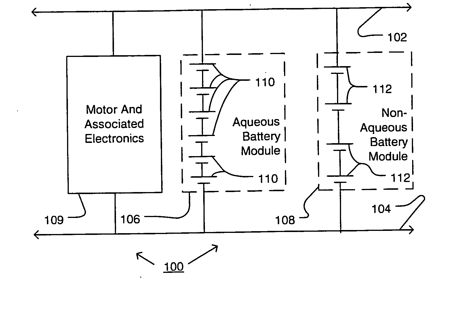
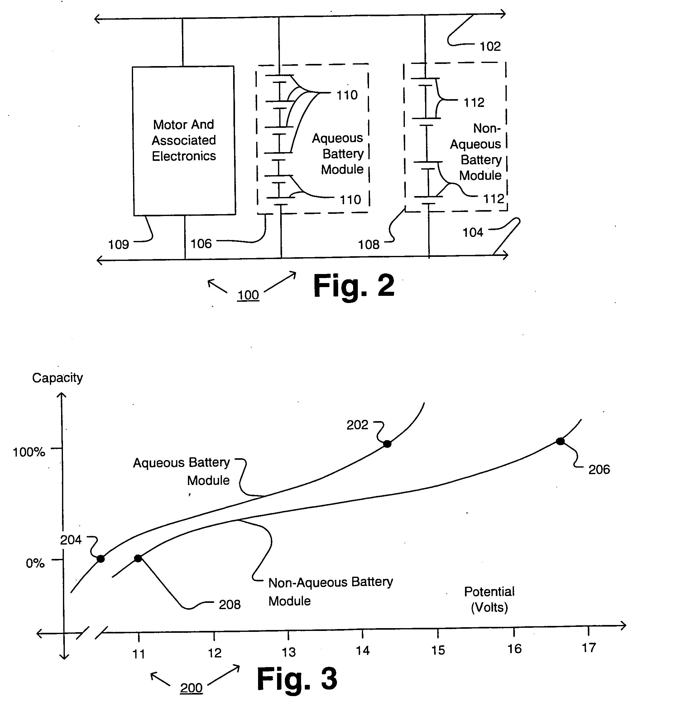
[0029]FIG. 2 is a first embodiment of power storage circuitry 100 for storing electrical power used to drive an electric driving motor of a battery powered vehicle (“BPV”). Preferably, the BPV has no need for an internal combustion engine or fuel cell or other on-vehicle energy source because it can store sufficient electrical energy in its battery modules. However, the present invention has broader application to internal combustion-battery hybrid vehicles, fuel cell-battery hybrid vehicles and the like. Preferably, the BPV is an LSBPV. That is because: (1) LSBPVs are increasingly popular; (2) LSBPVs are energy efficient, yet convenient for the user, relative to other transport solutions; (3) LSBPVs can be cheaper to make and / or maintain than larger battery powered vehicles; and (4) the electronics included in many conventional LSBPV designs (specifically, the power rails and associated electronics discussed below) are especially compatible with the present invention. However, the ...


PUM


Abstract

Battery system with multiple electrochemical cell types, wherein one cell type(s) (e.g., aqueous electrochemical cells) provides overvoltage protection for other cell type(s) (e.g., lithium ion superpolymer electrochemical cells). Battery system for a BPV with interchangeable modules of two or more 1:1 replaceable types, wherein each type of module has a different type, or combination, of electrochemical cells. For example, one battery module type may contain aqueous cells suitable for overvoltage protection and high power operation, while another battery module may include lithium ion superpolymer cells for their large capacity and high energy density. Use of lithium ion superpolymer electrochemical cells in low speed battery powered vehicles.

Description

RELATED APPLICATION DATA [0001] This application claims any and all applicable benefits based on the following provisional patent application(s): (1) U.S. patent application No. 60 / 618,087 filed on 16 May 2005; and (2) U.S. patent application No. 60 / 686,413 filed on 2 Jun. 2005. All of the foregoing patent-related documents are herein incorporated by reference.FIELD OF THE INVENTION [0002] The present invention relates to electric battery systems for power storage and more particularly to electric battery systems for battery powered vehicles (“BPVs,” see DEFINITIONS section for a definition) and even more particularly to electric battery systems for low speed battery powered vehicles (“LSBPVs,” see DEFINITIONS section for a definition). DESCRIPTION OF THE RELATED ART [0003] BPVs are conventional. One BPV design is shown in U.S. Pat. No. 6,331,365 (“'365 King”) at FIG. 7. The BPV of FIG. 7 of '365 King includes a lithium ion, high energy density energy battery and a high power densit...

Claims


Application Information

Patent Timeline
IPC IPC(8): B60L11/18H01M16/00H01M10/40H01M10/052H01M10/0565H01M10/36
CPCB60L3/0046B60L3/0053B60L11/1868H01M6/5033H01M10/052H01M10/0565Y02T10/7005H01M16/00Y02T10/7011Y02T10/7016Y02T10/7066Y02T90/34B60L2200/26H01M10/06B60L58/14B60L58/15B60L58/20B60L58/21Y02E60/10Y02T10/70Y02T90/40
Inventor DASGUPTA, SANKARBHOLA, RAKESH
Owner DASGUPTA SANKAR
Why Eureka
Try Eureka