Voltage source inverter control method

Inactive Publication Date: 2007-02-08
YASKAWA DENKI KK
View PDF3 Cites 14 Cited by
  • Summary
  • Abstract
  • Description
  • Claims
  • Application Information

AI Technical Summary

Benefits of technology

[0032] According to the present invention, since the dispersion value for the dead time can be easily and accurately calculated, an unstable phenomenon, which occurs due to waveform distortion and torque ripple that are caused by the dispersion of the dead time, can be prevented, and stable control can be provided.

Problems solved by technology

Therefore, when there is a dead time difference between the P side and N side switching devices, a satisfactory correction can not be performed, and to perform an adjustment, the motor must be driven by supplying two or more different switching frequencies (carrier frequencies).

Method used


Image

  • Voltage source inverter control method
  • Voltage source inverter control method
  • Voltage source inverter control method

Examples


embodiment 1

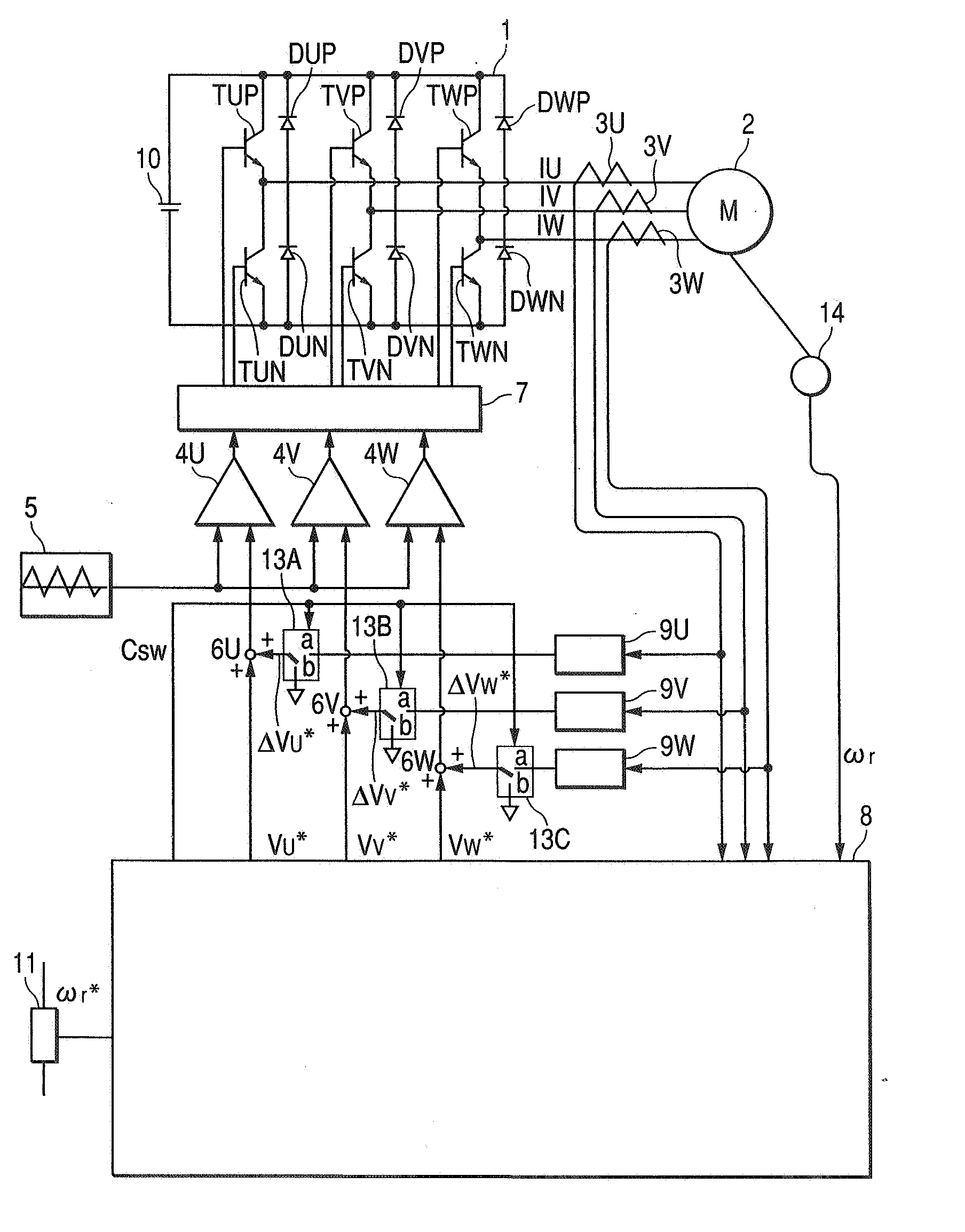
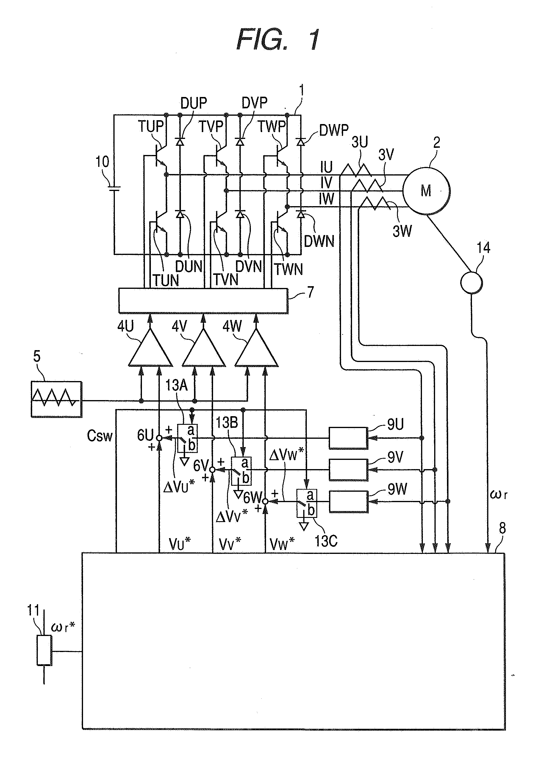
[0063] A first embodiment of the present invention is shown in FIG. 1. In FIG. 1, reference numeral 1 denotes a voltage source inverter; 2, an AC motor; 3U, 3V, 3W, current detectors; 4U, 4V, 4W, comparators; 5, an oscillator for oscillating a carrier signal; 6U, 6V, 6W, adders; 7, a gate drive circuit; 8, an inverter controller; 9U, 9V, 9W, dead time compensators; 10, a DC power source; 11, a speed instruction circuit; and 13A, 13B, 13C, switch circuits. The voltage source inverter 1 employs a PWM control method to convert a DC voltage, received from the DC power source 10, to an AC voltage having an arbitrary frequency. The voltage source inverter 1 includes: switching devices TUP, TVP, TWP, TUN, TVN, TWN, which are formed of transistors and power semiconductor devices such as IGBT; and feedback diodes DUP, DVP, DWP, DUN, DVN, DWN, which are connected in an antiparallel manner to the individual power semiconductor devices. The AC motor 2 is connected to the AC output terminals of ...

embodiment 2

[0079] A second embodiment will now be described. According to the second embodiment, an operation is performed while a voltage correction value is varied in such phases that the current detection values of two of a U phase, W phase and W phase are equal, and when the current detection values of the two phases match, or when two times the current of the other phase is supplied to one phase, a difference value for the voltage correction value is stored as a dispersion value (relative value) between the two phases. Under this condition, measurement of the dispersion value between phases on the same side, P or N, is performed.

[0080] Since the difference in the second embodiment from the first embodiment is only the provision of the phase θ and an adjustment method, these portions will be explained while referring to the flowchart in FIG. 4.

[0081] In the dispersion measurement processing performed before the operation starts, the dispersion tuning processor 24 performs (block 3a) and ...


PUM


Abstract

A simple and accurate dead time dispersion measurement method and a voltage source inverter control method that can prevent the occurrence of an unstable phenomenon are provided. The control method controls a voltage source inverter of a PWM system, which includes a power semiconductor device controlling a level of a voltage, a frequency and a phase. According to the control method, before operation, voltage error information for each polarity of respective phase currents of the inverter is stored. And during the operation, the voltage error information is read to compensate for a voltage instruction value or a pulse width of a PWM instruction signal, so that a voltage error can be corrected.

Description

BACKGROUND OF THE INVENTION [0001] 1. Field of the Invention [0002] The present invention relates to a control method of an AC motor for preventing torque reduction and torque ripple, and an unstable phenomenon in a voltage source inverter of a PWM system. [0003] 2. Description of the Related Art [0004] In a voltage source inverter of a PWM system, a P side switching device and an N side switching device constituting the inverter are alternately rendered conductive to control an output voltage. However, since due to the turn-off time a delay occurs in the switching of the switching devices, only one of the switching devices is turned on when a predetermined period (a dead time) has elapsed following the switching off of the other switching device, and the P side and the N side switching devices are not turned on at the same time. [0005] In the related voltage source inverter of the PWM system, especially in a case wherein the output frequency of the inverter is low, simply because t...

Claims


Application Information

Patent Timeline
IPC IPC(8): H02M1/12H02M7/5387
CPCH02M7/53873H02P27/08H02M7/5395H02M7/53871
Inventor YAMAMOTO, YOICHITANAKA, MASASHIRONAKAMURA, SHIGEKAZUSUETAKE, HIROSHI
Owner YASKAWA DENKI KK
Why Eureka
Try Eureka