Borehole telemetry system

a telemetry system and borehole technology, applied in the field of borehole telemetry system, can solve the problems of high telemetry rate, inability to justify high cost, and inability to use mwd techniques in operations,

Inactive Publication Date: 2007-02-08
SCHLUMBERGER TECH CORP
View PDF18 Cites 72 Cited by
  • Summary
  • Abstract
  • Description
  • Claims
  • Application Information

AI Technical Summary

Benefits of technology

[0022] It is seen as an advantage of the present invention that a plurality of down-hole measurements can be performed simultaneously with the resulting measurements being encoded into a digital bit stream that is subsequently used to modulate the carrier wave. The modulated carrier wave travels in direction of the surface where it is registered using appropriate sensors.
[0023] These and other aspects of the invention will be apparent from the following detailed description of non-limitative examples and drawings.

Problems solved by technology

One of the more difficult problems associated with any borehole is to communicate measured data between one or more locations down a borehole and the surface, or between down-hole locations themselves.
While much effort has been spent on “wireline” communication, its inherent high telemetry rate is not always needed and very often does not justify its high cost.
This requirement however prevents the use of MWD techniques in operations during which a flowing medium is not available.
Most of these known approaches are either severally limited in scope and operability or require down-hole transmitters that consume a large amount of energy.

Method used


Image

  • Borehole telemetry system
  • Borehole telemetry system
  • Borehole telemetry system

Examples


Embodiment Construction

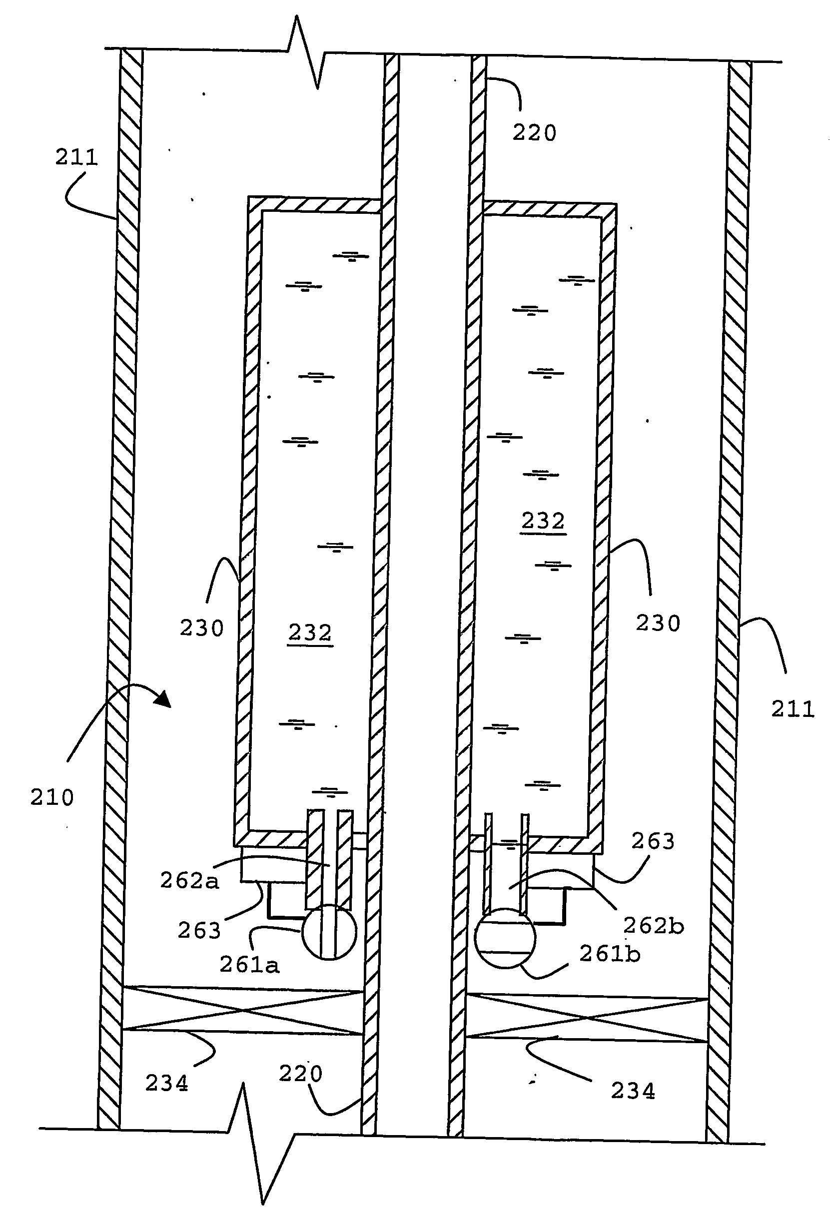
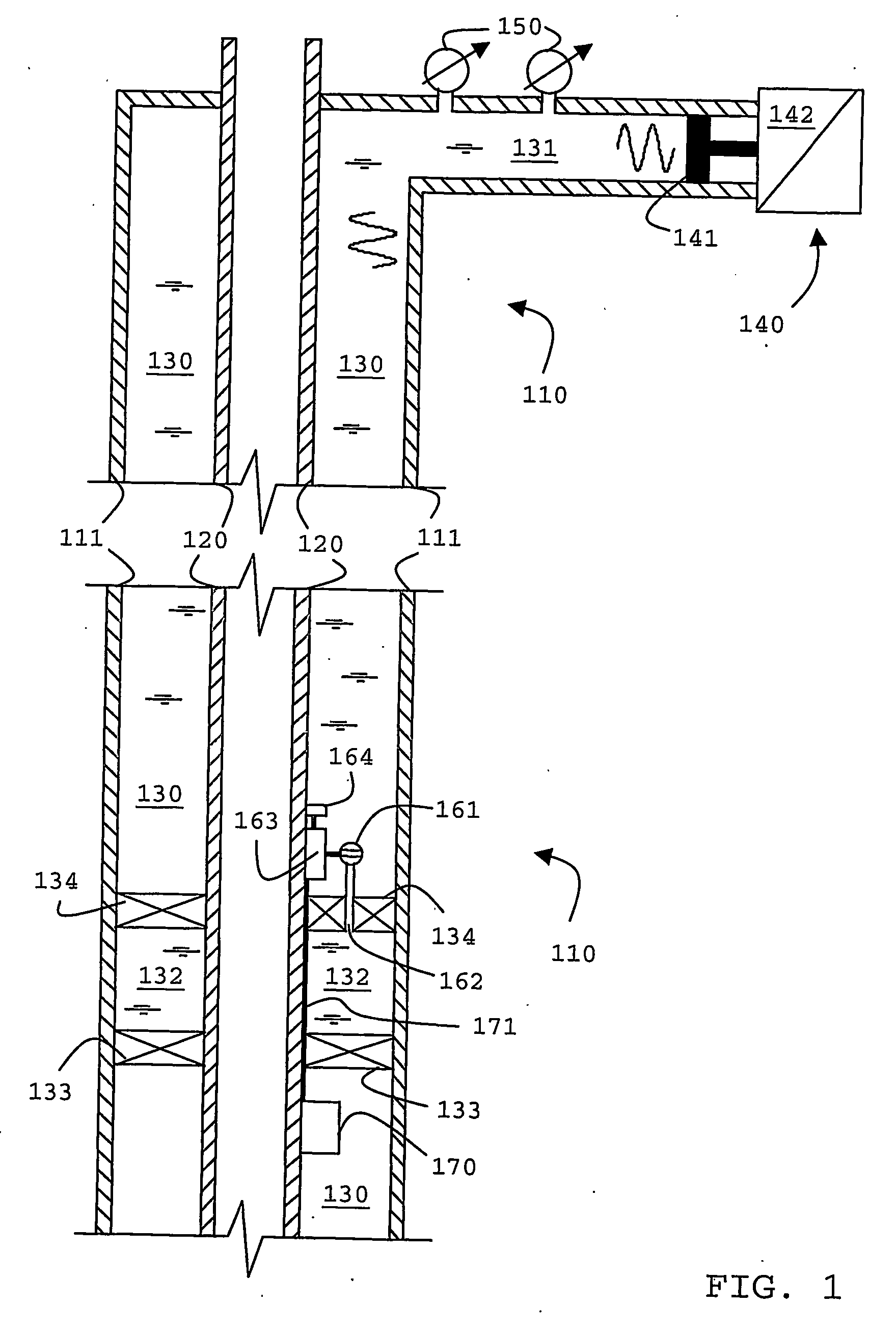
[0032] Referring first to the schematic drawing of FIG. 1, there is shown a cross-section through a cased wellbore 110 with a work string 120 suspended therein. Between the work string 120 and the casing 111 there is an annulus 130. During telemetry operations the annulus 130 is filled with a low-viscosity liquid such as water. A surface pipe 131 extends the annulus to a pump system 140 located at the surface. The pump unit includes a main pump for the purpose of filing the annulus and a second pump that is used as an acoustic wave source. The wave source pump includes a piston 141 within the pipe 131 and a drive unit 142. Further elements located at the surface are sensors 150 that monitor acoustic or pressure waveforms within the pipe 131 and thus acoustic waves traveling within the liquid-filled column formed by the annulus 130 and surface pipe 131.

[0033] At a down-hole location there is shown a liquid filled volume formed by a section 132 of the annulus 130 separated from the r...


PUM


Abstract

An acoustic telemetry apparatus and method for communicating encoded digital data from a down-hole location through a borehole to the surface is described including an acoustic channel terminated at a down-hole end by a reflecting terminal (133, 134), an acoustic wave generator (140) located at the surface and providing an acoustic wave carrier signal through said acoustic, channel, a modulator (162, 163) located down-hole to modulate amplitude and / or phase of said carrier wave in response to an encoded digital signal and one or more sensors (150) located at the surface adapted to detect amplitude and / or phase related information of acoustic waves traveling within said acoustic channel to determine the encoded digital data.

Description

[0001] The present invention generally relates to an apparatus and a method for communicating parameters relating to down-hole conditions to the surface. More specifically, it pertains to such an apparatus and method for acoustic communication. BACKGROUND OF THE INVENTION [0002] One of the more difficult problems associated with any borehole is to communicate measured data between one or more locations down a borehole and the surface, or between down-hole locations themselves. For example, communication is desired by the oil industry to retrieve, at the surface, data generated down-hole during operations such as perforating, fracturing, and drill stem or well testing; and during production operations such as reservoir evaluation testing, pressure and temperature monitoring. Communication is also desired to transmit intelligence from the surface to down-hole tools or instruments to effect, control or modify operations or parameters. [0003] Accurate and reliable down-hole communicatio...

Claims


Application Information

Patent Timeline
Patent Type & Authority Applications(United States)
IPC IPC(8): H04H9/00G01V3/00H04H60/31E21B47/18
CPCE21B47/182E21B47/20
Inventor HUANG, SONGMINGMOMMONT, FRANCKTENNENT, ROBERT
Owner SCHLUMBERGER TECH CORP
Why Eureka
Try Eureka