
Request processing between failure windows

a request processing and failure window technology, applied in the field of apparatus and method to prevent the propagation of corrupted data packets, can solve the problem that data processing performed within the chip itself may often become the bottleneck

Inactive Publication Date: 2007-02-08
AVAGO TECH INT SALES PTE LTD
View PDF2 Cites 32 Cited by
  • Summary
  • Abstract
  • Description
  • Claims
  • Application Information

AI Technical Summary

Problems solved by technology

While the HT interface provides a high-speed chip-to-chip interface, data processing performed within the chips itself may often become the bottle neck.

Method used


Image

  • Request processing between failure windows
  • Request processing between failure windows
  • Request processing between failure windows

Examples


Embodiment Construction

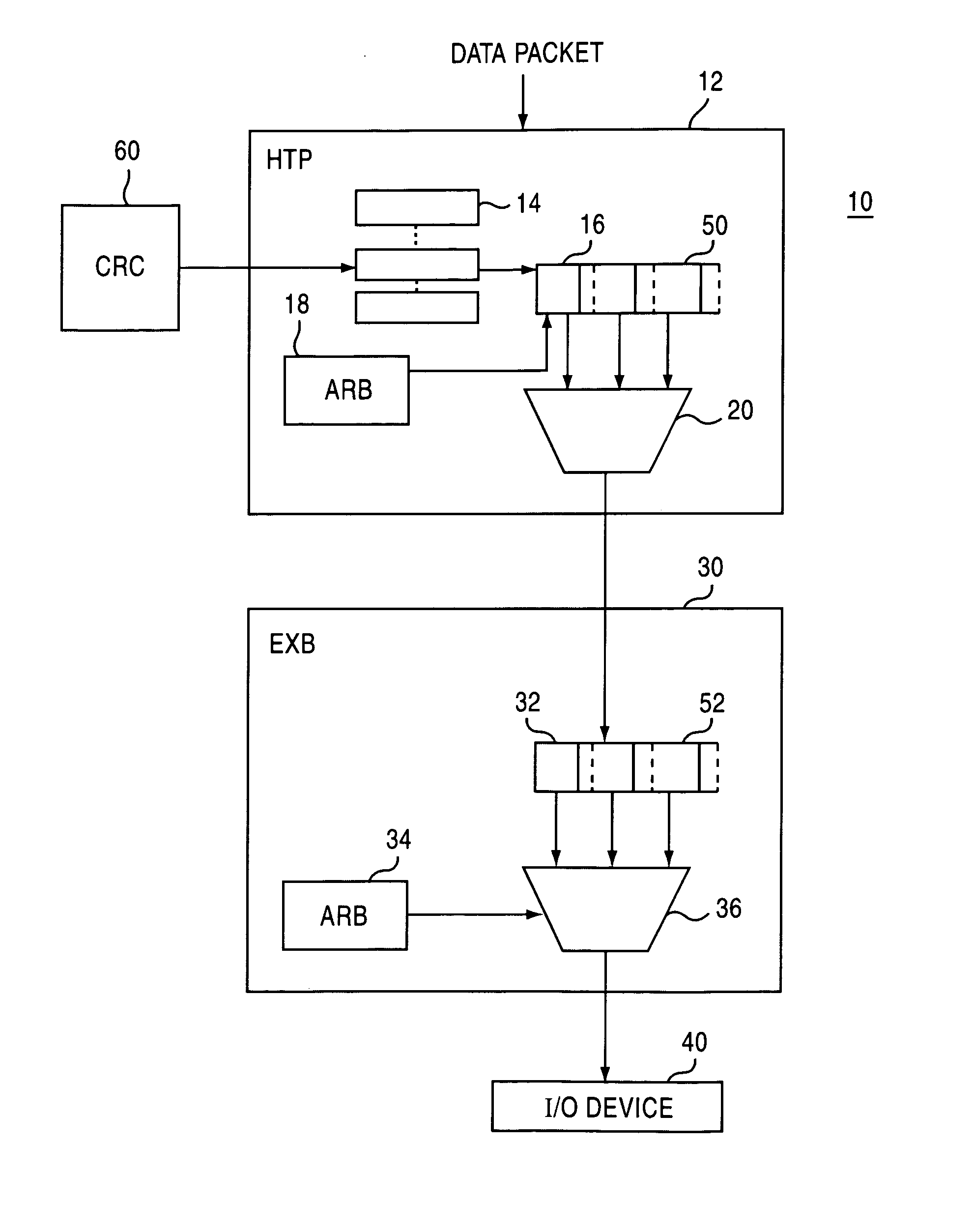
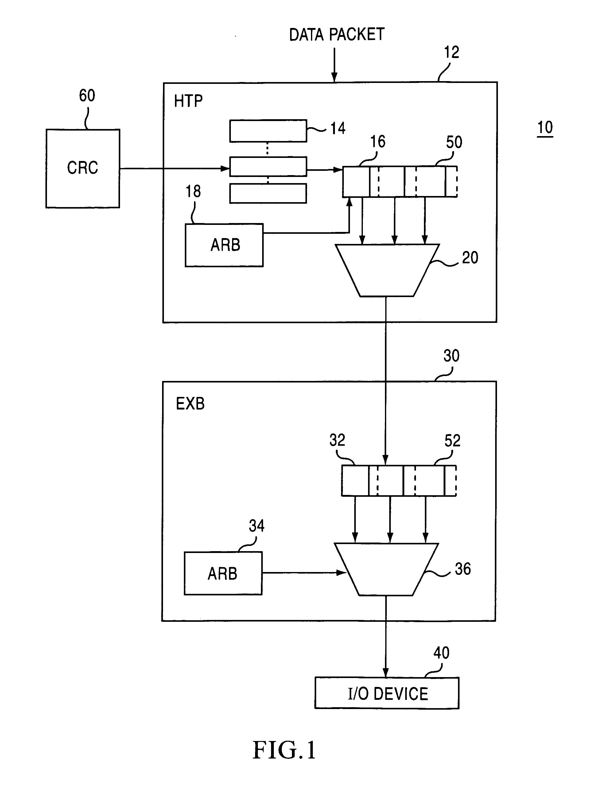
[0009] An apparatus and method for a chip for network devices is described. In one embodiment, the chip is a specially configured programmable chip such as a programmable logic device or a field programmable gate array. In another embodiment, the chip is an Application Specific Integrated Circuit (ASIC). In yet another embodiment, the chip is a general purpose processor augmented with anability to access and process interconnect packet traffic.

[0010] The chip may communicate with their respective I / O devices using link controllers complying with HyperTransport I / O Link Specification, and is able to achieve a throughput of 3.2 GB / sec when using a 1600 MHz data rate. HyperTransport technology is a packet-based link implemented on two independent unidirectional sets of wires. So for example some HyperTransport links may include both an output connection and an input connection. Each HyperTransport link is nominally point-to-point and connects two devices. Chains of HyperTransport link...


PUM


Abstract

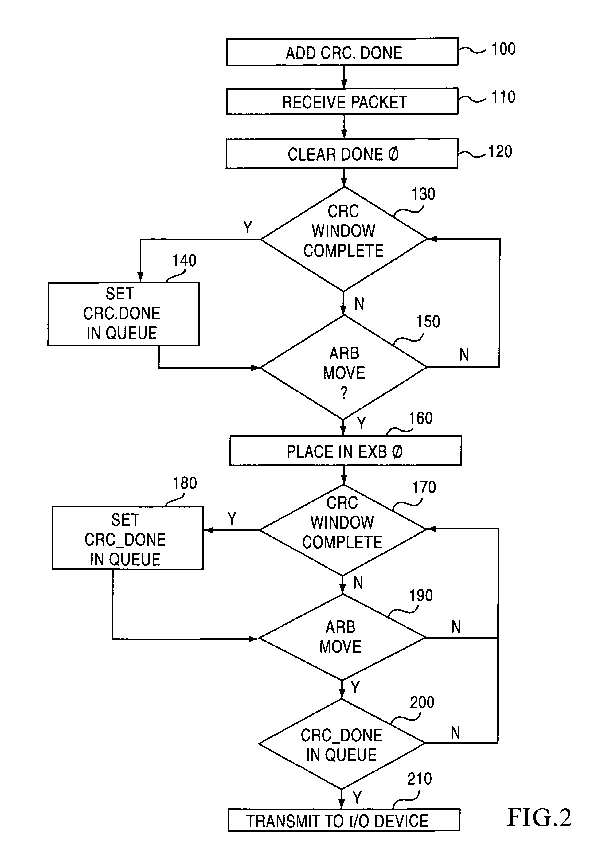
An apparatus and method are provided including a point-to-point cluster link configured to receive a data packet and determines a cyclic redundancy code check for the data packet. The point-to-point cluster link is configured to add a cyclic redundancy code check bit to the data packet transmitted to the point-to-point inter-cluster link, to clear the cyclic redundancy code check bit when the data packet is received, and to sample a cyclic redundancy code window to identify a corrupted data packet.

Description

BACKGROUND OF THE INVENTION [0001] 1. Field of the Invention [0002] The present invention relates to an apparatus and method to prevent propagation of corrupted data packets and, more particularly, to an apparatus and method adding an additional sideband signal to all entries in queues that a data packet transfers through and precluding a corrupted data packet from being transmitted to outside devices when the additional sideband signal is clear. [0003] 2. Description of the Related Art [0004] The HyperTransport (HT) technology was developed to provide a high-speed, high-performance point-to-point on-board link for interconnecting integrated circuits on a motherboard. The HT technology can be significantly faster than other bus technologies for an equivalent number of pins. The HT technology is designed to provide significantly more bandwidth than current technologies, to use low-latency responses, to provide low pin count, to be compatible with legacy computer buses, to be extensib...

Claims


Application Information

Patent Timeline
Patent Type & Authority Applications(United States)
IPC IPC(8): H04J3/00
CPCH04L1/0061H04L1/0045
Inventor MICHELS, PETER
Owner AVAGO TECH INT SALES PTE LTD
Learn More