Plastic hydraulic tensioner

a hydraulic tensioner and plastic technology, applied in the direction of belts/chains/gearrings, mechanical equipment, belts/chains/gears, etc., can solve the problems of difficult manufacturing, bolts that cannot be loosened, and complicated structural structure of plastic tensioners, so as to prevent oil leakage from the oil reservoir, prevent the effect of backlash noise, and reliably prevent the tensioner from being pressed

Inactive Publication Date: 2007-02-08
TSUBAKIMOTO CHAIN CO
View PDF8 Cites 1 Cited by
  • Summary
  • Abstract
  • Description
  • Claims
  • Application Information

AI Technical Summary

Benefits of technology

[0013] Thus, according to one aspect of the invention, in the formation of the tensioner body by insertion molding, the resin of the tensioner flows against the flat part or parts of the exterior surfaces of the bushings, or into one or more concave grooves on the exterior of the bushing, so that, in the completed tensioner, rotation of the bushings as a result of engine vibration, and resultant loosening of the tensioner mounting bolts, are avoided.
[0015] According to still another aspect of the invention, since the protrusion on the bushing portion extends from a flat surface of the bushing, or from a concave groove formed in the bushing, it can be formed in the process of cutting or machining the flat surface or groove simply by leaving a front portion of the bushing uncut or unmachined. If the protrusion is formed on the bushing at a location remote from the end of the bushing that engages the engine block, flotation of the tensioner can be reliably prevented.
[0016] With this invention, oil leakage from the oil reservoir can be prevented, a sufficient oil supply to the high pressure oil chamber can be maintained, and the generation of backlash noises in a timing chain, due to insufficiency of the holding force applied to the chain by the plunger, can be prevented.

Problems solved by technology

A typical plastic tensioner is structurally complicated, and is difficult to manufacture.
Vibrations of the engine can result in rotation of the bushing, which can, inturn, cause rotation of the bolt 22, causing the bolt to loosen.
Even very feeble vibrations can result in loosening of the mounting bolts in this manner.
Furthermore, insert-molding does not necessarily fix the tensioner body 2 firmly to the bushings.
When such leakage occurs, an adequate amount of oil may not be supplied to the high pressure oil chamber of the tensioner, and backlash in the chain drive can occur, resulting in the generation of backlash noise.

Method used


Image

  • Plastic hydraulic tensioner
  • Plastic hydraulic tensioner
  • Plastic hydraulic tensioner

Examples


Embodiment Construction

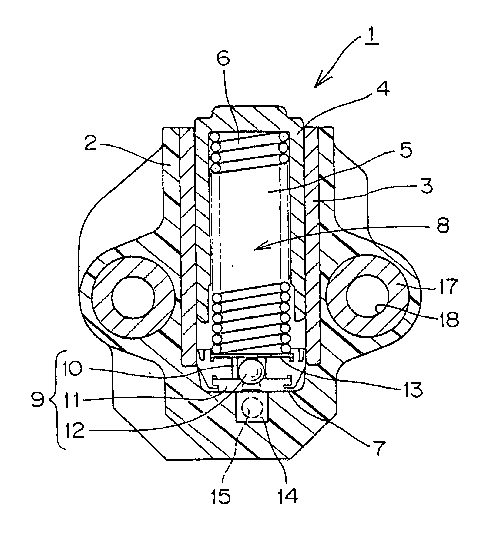
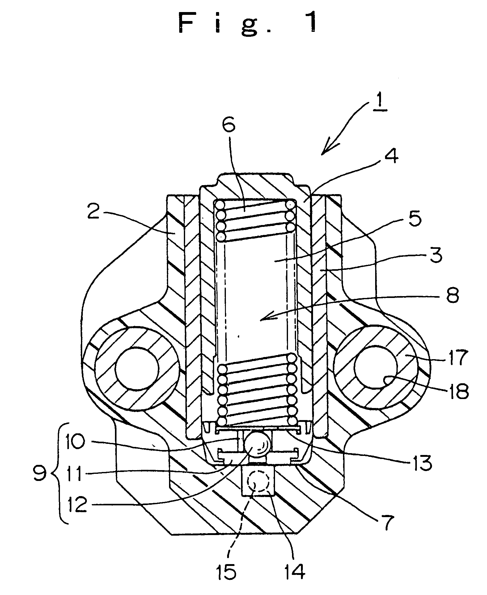
[0031] As shown in FIG. 1, in the plastic hydraulic tensioner 1 according to the invention, a cylindrical metal lining 3 is insert-molded in a plunger-receiving hole formed in a synthetic resin tensioner body 2. A hollow plunger 4 is slidable in the cylindrical lining 3. The plunger has a closed protruding end and an open rear end. A coil spring 6 extends through the open rear end of the plunger into the hollow part 5 of the plunger, and is in compression between the closed protruding end of the plunger, and the bottom 7 of the plunger-receiving hole. The coil spring urges the plunger in the protruding direction.

[0032] The closed protruding end of the plunger, the side wall of the plunger, part of the interior of the cylindrical metal lining 3, and a part of the bottom of the plunger-receiving hole below the bottom end of the metal lining, together form a high pressure oil chamber 8. A check valve 9 is provided at the bottom of the plunger-receiving hole to permit the flow of oil i...


PUM


Abstract

In a plastic hydraulic tensioner having an oil reservoir formed as a recess in a portion of a synthetic resin tensioner body adapted to engage a tensioner mounting surface on an engine block, metal bushings are insert-molded in the synthetic resin tensioner body for receiving mounting bolts by which the tensioner is secured to an engine block. The outer circumferential surface of each bushing is provided with at least one flat portion or at least one concave groove, and a protruding portion of the bushing is formed adjacent the end of the flat or groove remote from the engine block-contacting end of the bushing.

Description

CROSS-REFERENCE TO RELATED APPLICATION [0001] This application claims priority on the basis of Japanese patent application 2005-226825, filed Aug. 4, 2005. The disclosure of Japanese application 2005-226825 is hereby incorporated by reference. FIELD OF THE INVENTION [0002] This invention relates to a hydraulic tensioner of the kind used to maintain proper tension in the timing chain of an automobile engine. The invention relates more specifically to improvements in a plastic hydraulic tensioner in which one or more metal bushings are incorporated into a synthetic resin tensioner body in order to accommodate mounting bolts by which the tensioner is attached to an engine block. BACKGROUND OF THE INVENTION [0003] In most hydraulic tensioners currently in use, a ferrous metal plunger is arranged to protrude slidably from a tensioner body composed of a metal such as cast iron, aluminum alloy or the like. The metal tensioner body has a large mass. Reduction of the overall weight of the te...

Claims


Application Information

Patent Timeline
Patent Type & Authority Applications(United States)
IPC IPC(8): F16H7/08F16H7/22
CPCF16H7/0848F16H2007/0806F16H2007/0859F16H2007/0842F16H2007/0812
Inventor YOSHIDA, OSAMU
Owner TSUBAKIMOTO CHAIN CO
Why Eureka
Try Eureka