Guide wire with magnetically adjustable bent tip and method for using the same

a technology of guide wires and bent tips, which is applied in the field of guide wires, can solve the problems of frustrating the physician, increasing the difficulty of controlling guide wires, and disadvantages of pre-shaped bends, and achieves the effect of increasing the curvature of the distal tip

Inactive Publication Date: 2007-02-08
STEREOTAXIS
View PDF7 Cites 166 Cited by
  • Summary
  • Abstract
  • Description
  • Claims
  • Application Information

AI Technical Summary

Benefits of technology

[0005] The present invention relates to improvements in the construction of magnetically navigable medical guide wires to enable conventional navigation through simple vessel anatomy without the need for magnetic fields, and magnetic navigation through smaller complex vessel branches using an externally applied magnetic field. Generally, a guide wire constructed in accordance with the principles of this invention comprises an elongate wire having a proximal end and a distal end. The distal end further comprises one or more bent sections and one or more magnetically responsive elements disposed on the one or more bent sections of the guide wire. The magnetically responsive elements are preferably encapsulated or sealed by a radio-opaque material and secured to the bent section or sections by welding or with an adhesive. The magnetically responsive element is preferably comprised of a permanent magnetic material, but may alternatively comprise a permeable magnetic mater...

Problems solved by technology

At the same time, the pre-shaped bends can become a disadvantage when the tip must access small vessels in the vasculature system or passages in the coronary anatomy.
Furthermore, after the pre-shaped guide wire has made several bends, the guide wire becomes increasingly difficult to control, requiring repeated attempts to enter a desired vessel branch or gain passage through an occlusion.
This...

Method used


Image

  • Guide wire with magnetically adjustable bent tip and method for using the same
  • Guide wire with magnetically adjustable bent tip and method for using the same
  • Guide wire with magnetically adjustable bent tip and method for using the same

Examples


Embodiment Construction

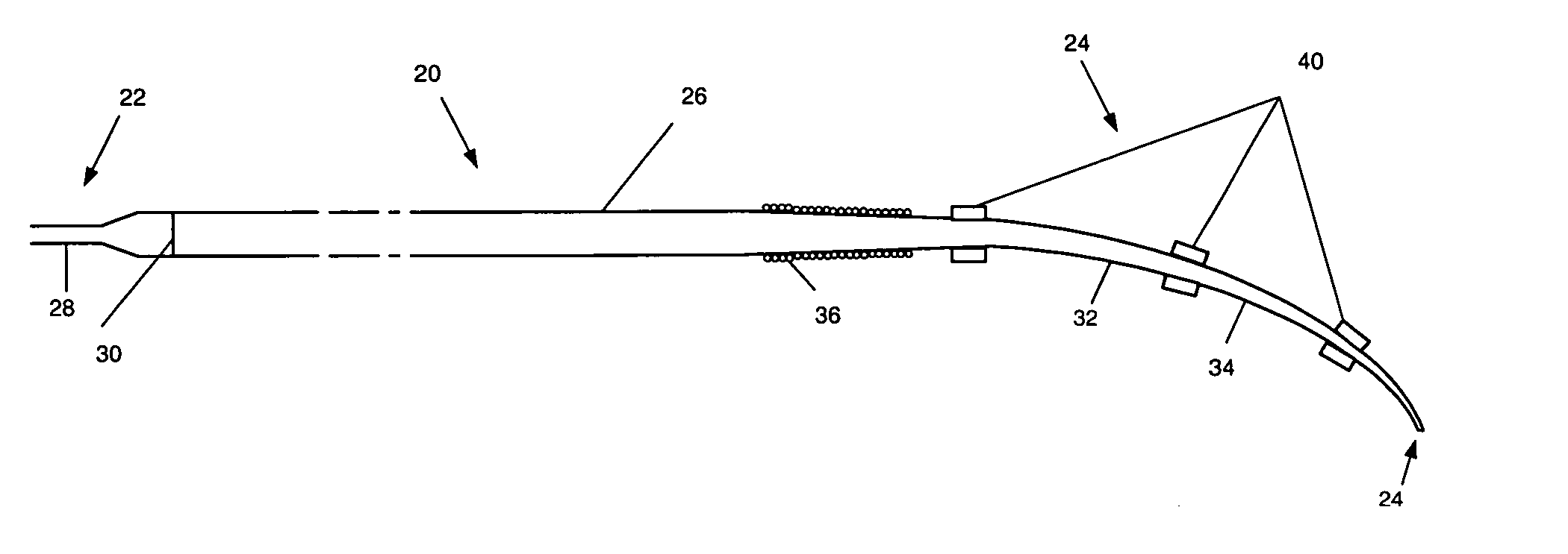
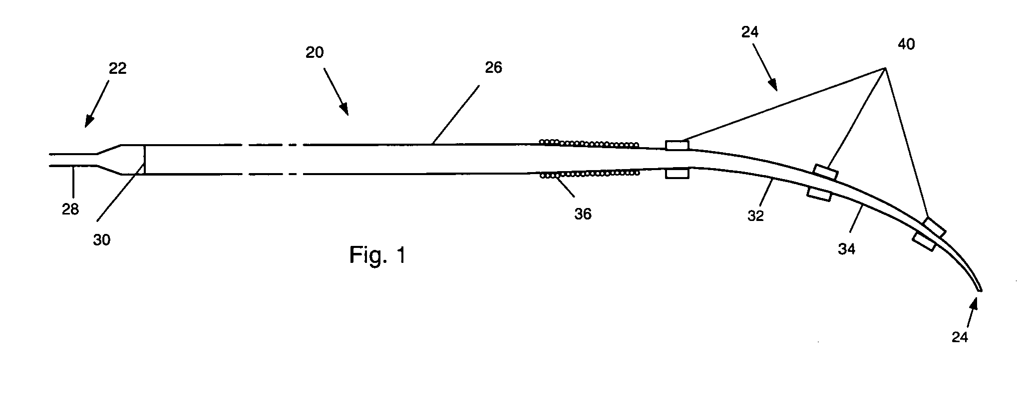
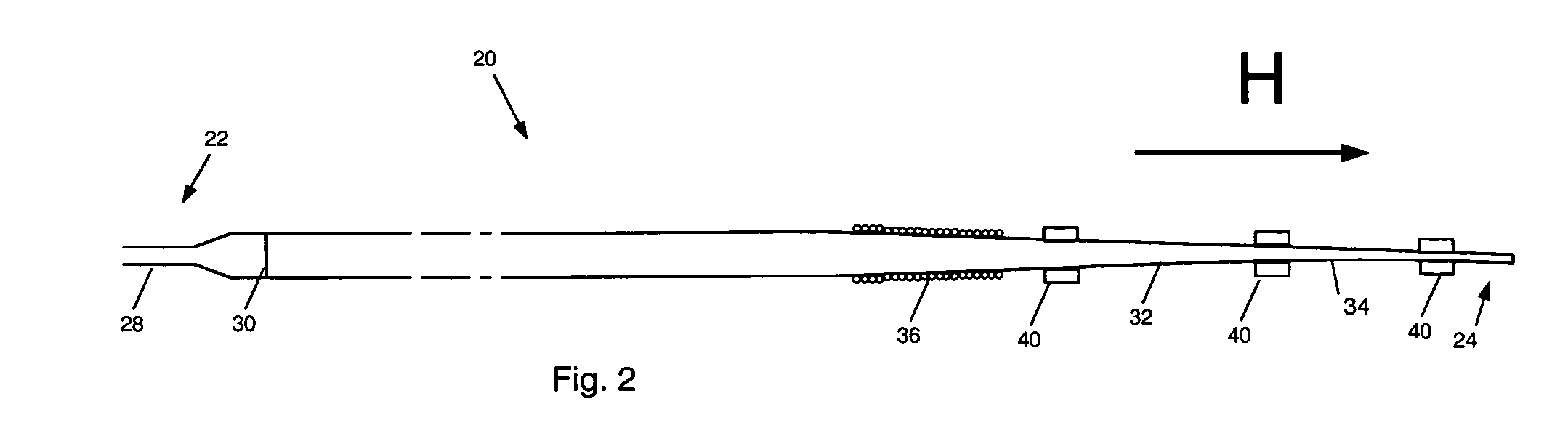
[0014] A first preferred embodiment of a magnetically navigable medical guide wire in accordance with the principles of this invention is indicated generally as 20 in FIG. 1. The guide wire 20 has a proximal end 22 and a distal end 24 and comprises a flexible core wire 26 extending from the proximal end substantially to the distal end. In the first preferred embodiment, the core wire 26 is between about 40 cm and about 350 cm, and tapers from a diameter of about 0.3 mm at the proximal end to about 0.05 mm at the distal end. In the preferred embodiment the bend 32 forms a bent distal section 34 that bends at an angle of between about 15 and about 90 degrees, and more preferably between about 20 and about 60 degrees.

[0015] The core wire 26 can be made of Nitinol, stainless steel or other suitable material, and may comprise a tapered cross-section that provides for increased flexibility near the tip of the guide wire. Additionally, the core wire can have a flat, malleable section that...


PUM


Abstract

The guide wire invention relates to improvements in magnetically navigable medical guide wires for enabling, in addition to magnetic navigation, conventional navigation without the use of a magnetic field. The distal portion of the guide wire may be navigated by either manually applying an axial rotation to the guide wire or by applying a magnetic field to modify the curvature of the distal portion to access small branch vessels in a subject body. The distal portion of the guide wire can also be straightened or aligned with the longitudinal axis of the guide wire by applying a magnetic field that straightens the bent section in the direction of the longitudinal axis, which enables the guide wire to push through a lesion.

Description

CROSS-REFERENCE TO RELATED APPLICATIONS [0001] This application claims the benefit of U.S. provisional patent application Ser. No. 60 / 642,583 filed Jan. 10, 2005, the entire disclosure of which is incorporated herein by reference.FIELD OF THE INVENTION [0002] This invention relates to guide wires for navigation of medical devices through body lumens such as blood vessels, and in particular to magnetically navigable guide wires for use in the vasculature. BACKGROUND OF THE INVENTION [0003] Navigation of a conventional guide wire involves rotating or applying a torque to the proximal end of the guide wire repeatedly to rotate the bent end of the distal tip while the wire is pushed. This action is repeated until, by trial and error, the tip enters the desired vessel branch. In navigating through the vasculature of the body, the distal end of the conventional guide wire often comprises one or more bends that improve navigation through the vessels necessary to reach the target area for t...

Claims


Application Information

Patent Timeline
IPC IPC(8): A61M25/00A61M31/00
CPCA61B2017/00876A61M25/0127A61M25/0158A61M2025/09183A61M2025/09083A61M2025/09133A61M25/09
Inventor SELL, JONATHAN C.
Owner STEREOTAXIS
Why Eureka
Try Eureka