Delivery mechanism for implantable stent

a delivery mechanism and stent technology, applied in the field of implantable medical devices, can solve the problems of reducing or complete loss of functional attributes, difficult to maintain steady, awkward operation, etc., and achieve the effects of convenient and precise stent positioning, convenient operation, and smooth retractability

Inactive Publication Date: 2007-02-08
BARD PERIPHERAL VASCULAR
View PDF101 Cites 70 Cited by
  • Summary
  • Abstract
  • Description
  • Claims
  • Application Information

AI Technical Summary

Benefits of technology

[0006] The present invention is directed to a stent delivery mechanism which is both easy to operate and facilitates extremely precise stent positioning. Several different configurations are described. For example, in a first embodiment, a simple V-shaped grip aligned generally longitudinally with the catheter to be deployed is utilized. A mechanical advantage gear mechanism is employed, which operates in conjunction with a ratchet to smoothly retract a sheath hub to which the outer sheath of the catheter is attached. The mechanism is easy to grasp and actuate in any rotational configuration. The V-shaped mechanism includes a body which contains the ratchet and a drive gear lever handle. The lever handle interacts with a drive pinion to drive the ratchet by a predetermined amount, thus retracting the sheath hub by a corresponding amount. The drive gear lever handle mechanism provides both the mechanical advantage, which results in movement of the outer sheath by a relatively small amount for a large displacement of the lever handle, and a much smoother operation than the direct ratchet operation of the prior art device.
[0007] In a second embodiment of the invention employs a hydraulic mechanism to both provide the mechanical advantage and achieve extremely smooth retraction operation. In addition, the use of hydraulics, as opposed to other systems, creates positive positioning so that the actuator will not cause any unexpected motion. The hydraulic system may be actuated by means of a drive plunger similar to the operation of a syringe, or may be equipped with a lever handle to allow a gripping action to be employed for actuation.
[0008] In a third embodiment, a rack and pinion drive system operated by a thumb wheel is employed. The rack and pinion drive system also provides a desirable mechanical advantage and promotes smooth operation.
[0009] In a fourth embodiment, a power screw drive system is employed. This drive system is actuated by a thumb driven concentric drive knob which rotates to retract an internal power screw to which the outer sheath is secured. Again, a mechanical advantage is provided to promote smooth retraction of the outer sheath.
[0010] In order to further facilitate the stent deployment, the inner lumen of the delivery system may be formed of a metal spring, which is contained in its fully compressed state. The use of such a spring for the inner lumen provides significant advantages in that it is extremely flexible, enabling introduction of the catheter into the body and proper positioning of the stent, and yet is very rigid and non-compressible so as to maintain the stent in the desired position during outer sheath retraction.

Problems solved by technology

Various diseases of blood vessels or hollow organs cause a stenosis or complete occlusion of their lumen, which results in a decrease or complete loss of their functional attributes.
This mechanism has drawbacks in that it is awkward to operate and difficult to maintain steady so that the stent graft does not migrate away from its desired position during sheath retraction.

Method used


Image

  • Delivery mechanism for implantable stent
  • Delivery mechanism for implantable stent
  • Delivery mechanism for implantable stent

Examples


first embodiment

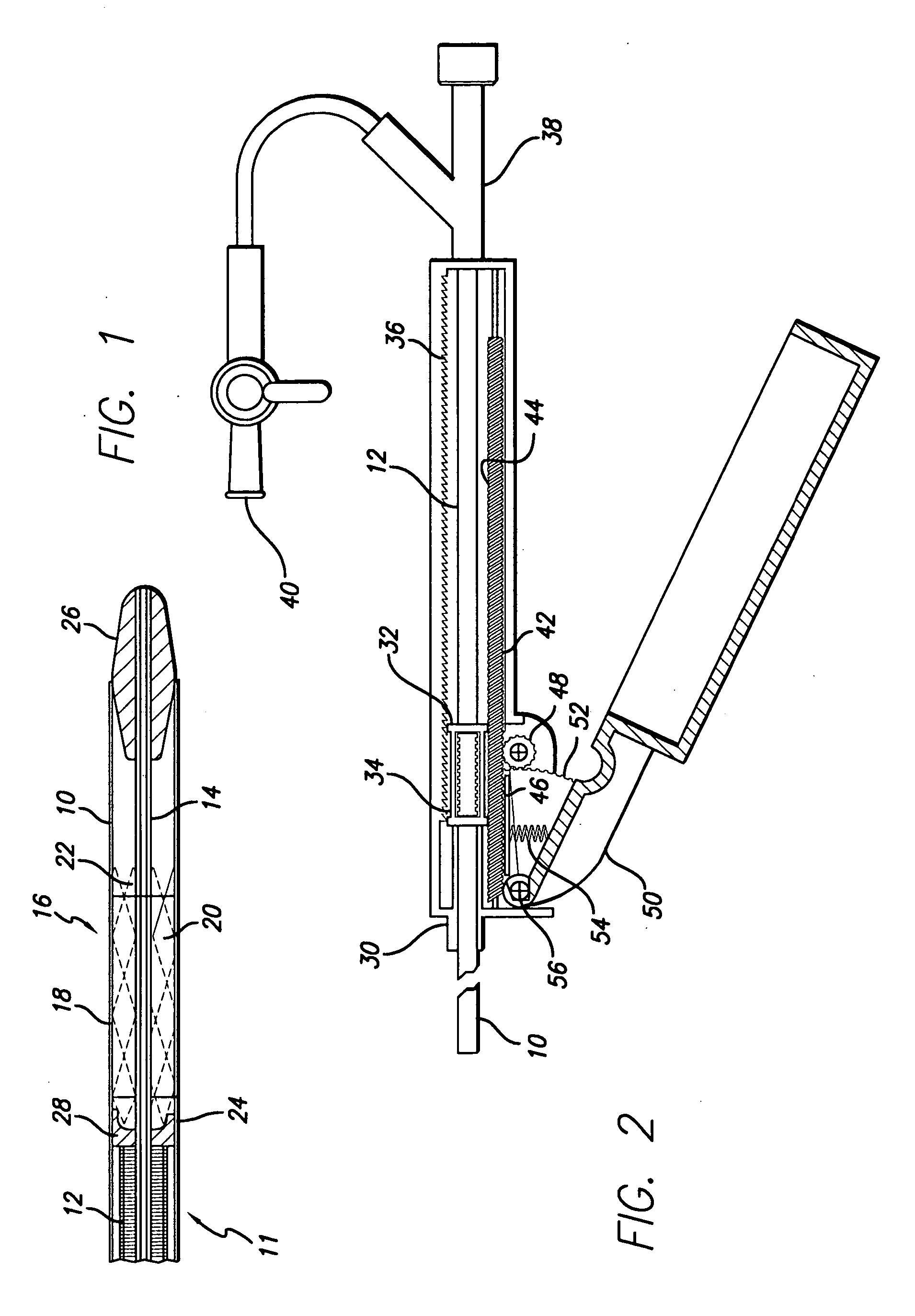
[0013]FIG. 2 is a cross-sectional view of the stent delivery mechanism of the present invention incorporating a moving rail mechanism;

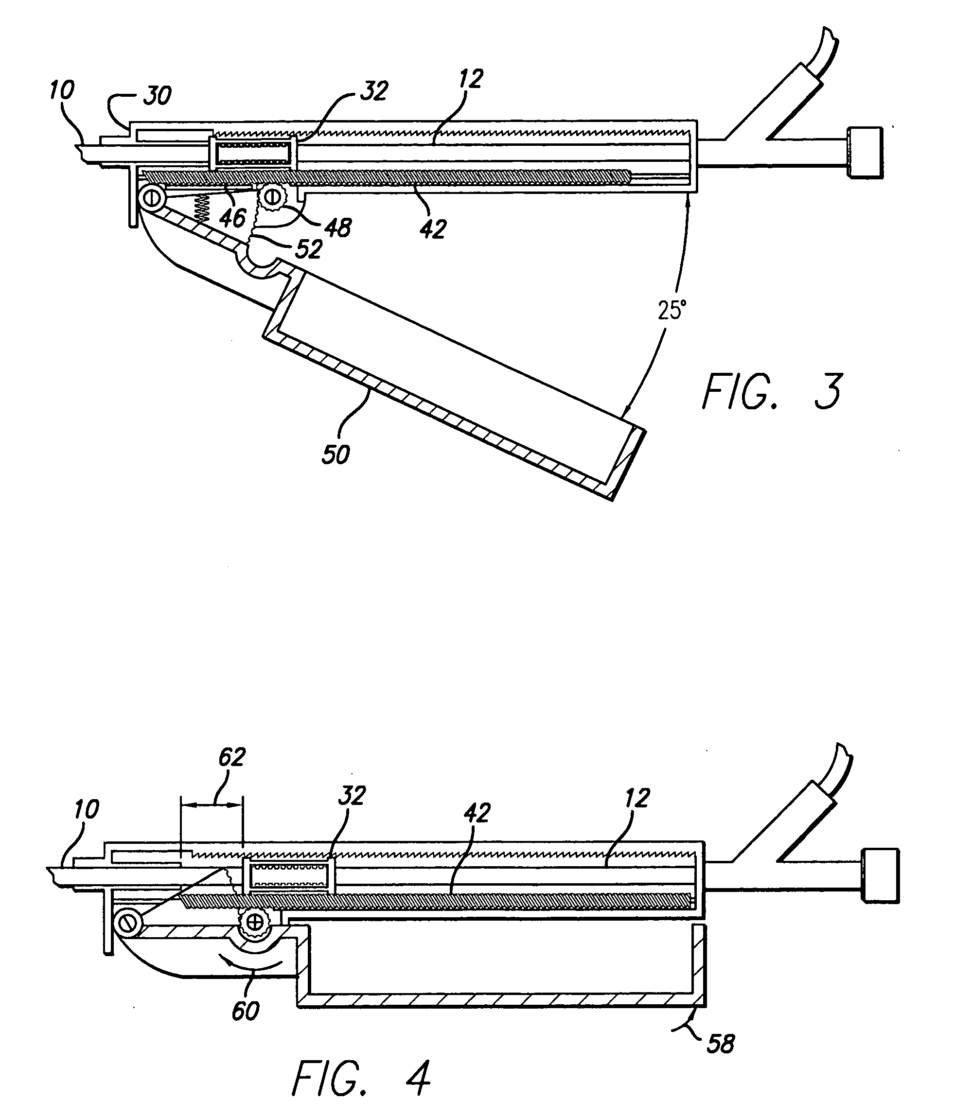
[0014]FIGS. 3-6 are cross-sectional views illustrating the retraction operation of the moving rail system;

[0015]FIG. 7 is an exploded view of a preferred embodiment of the stent delivery mechanism shown in FIG. 2.

second embodiment

[0016]FIG. 8 is a cross-sectional view of the stent delivery mechanism of the present invention incorporating a hydraulic mechanism

[0017]FIGS. 9-12 are cross-sectional views illustrating the operation of the embodiment of FIG. 7;

third embodiment

[0018]FIG. 13 is a cross-sectional view of the stent delivery mechanism of the present invention employing a rack and pinion thumb actuated drive system;

[0019]FIG. 14 is a view of the system of FIG. 13 along line 14-14;

[0020]FIGS. 15 and 16 are cross-sectional views illustrating the operation of the drive system of FIG. 13;


PUM


Abstract

A delivery system including an inner catheter with a reinforcing element and an outer catheter having a proximal end attached to a movable member. An abutment element may be attached to a distal end of the reinforcing element, configured to engage an implantable device disposed between the inner catheter and the outer catheter.

Description

PRIORITY [0001] This application is a continuation of U.S. application Ser. No. 10 / 357,985, filed Feb. 4, 2003, now U.S. Pat. No. 7,122,050, which is a continuation of U.S. application Ser. No. 09 / 409,210, filed Nov. 30, 1999, now U.S. Pat. No. 6,514,261, which claims the benefit of U.S. Provisional Application No. 60 / 102,498, filed Sep. 30, 1998, each of which are incorporated by reference into this application as if fully set forth herein.FIELD OF THE INVENTION [0002] The present invention relates to implantable medical devices. More particularly, the present invention relates to mechanisms for implanting a self-expanding stent graft which is used to sustain a weakened body vessel. BACKGROUND [0003] Various diseases of blood vessels or hollow organs cause a stenosis or complete occlusion of their lumen, which results in a decrease or complete loss of their functional attributes. Various implantable prosthetic devices for sustaining a blood vessel or hollow organ lumen typically ha...

Claims


Application Information

Patent Timeline
Patent Type & Authority Applications(United States)
IPC IPC(8): A61F2/06A61F2/95
CPCA61F2/95A61F2/966A61F2002/9517A61F2/9517
Inventor BROOKS, CHRISTOPHER J.MCCREA, BRENDAN J.RANDALL, SCOTT L.VAN ROYEN, DONALD
Owner BARD PERIPHERAL VASCULAR
Why Eureka
Try Eureka