Antirotation injection system for turbojet

Active Publication Date: 2007-02-15
SN DETUDE & DE CONSTR DE MOTEURS DAVIATION S N E C M A
View PDF7 Cites 17 Cited by
  • Summary
  • Abstract
  • Description
  • Claims
  • Application Information

AI Technical Summary

Benefits of technology

[0007] The subject of the present invention is precisely an injection system for a gas turbine engine, particularly

Problems solved by technology

Specifically, this rotation, when it may occur, causes rapid wear of the parts and considerably reduces their service life.
Nevertheless, the clearance is sufficiently small to prevent a compl

Method used


Image

  • Antirotation injection system for turbojet
  • Antirotation injection system for turbojet
  • Antirotation injection system for turbojet

Examples


Embodiment Construction

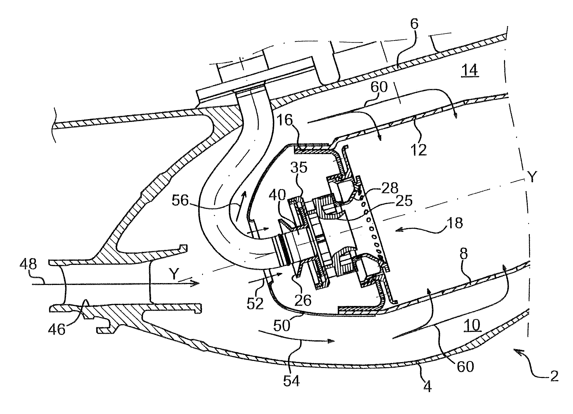
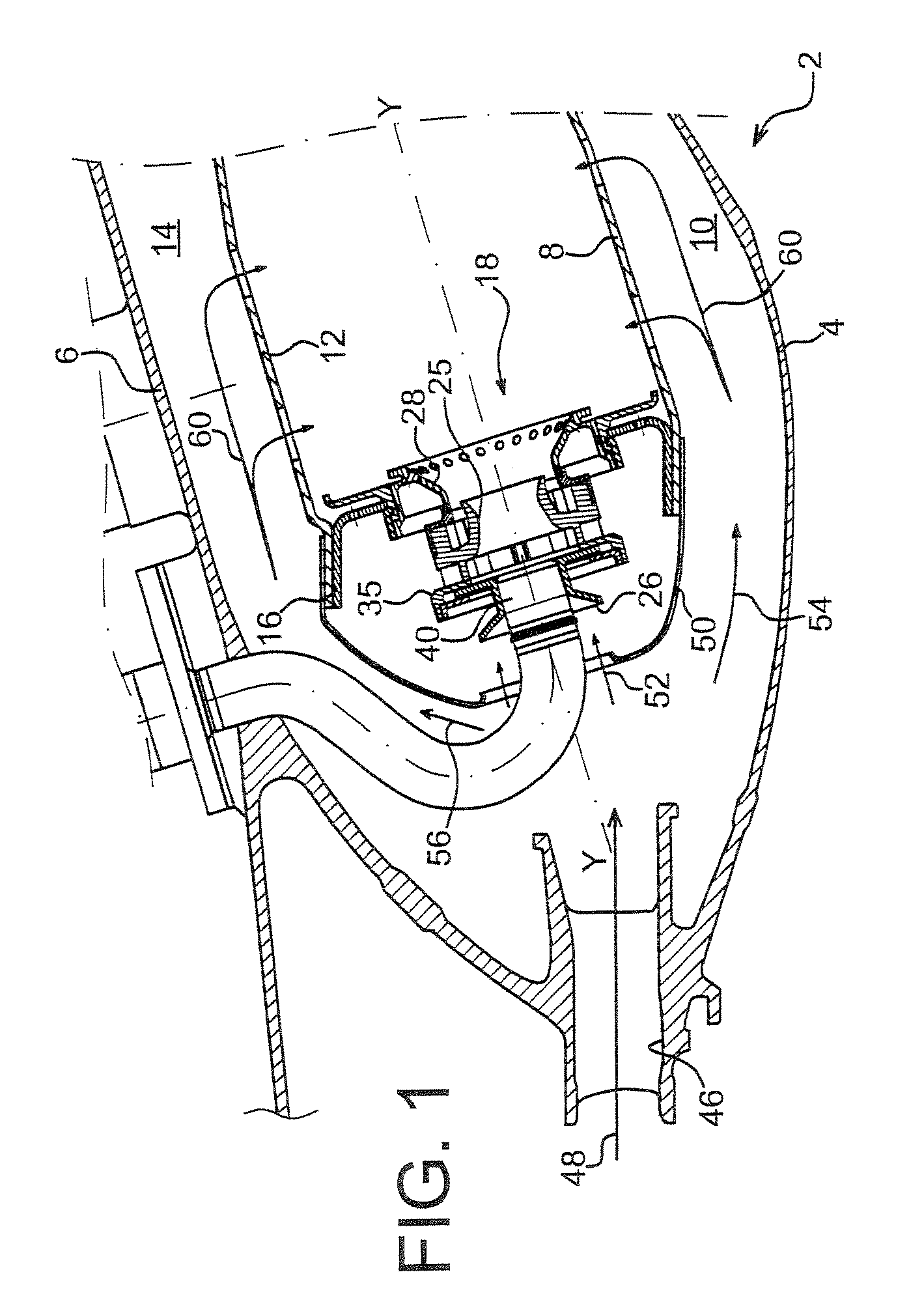
[0019]FIG. 1 shows a partial schematic view, in section, of a turbojet combustion chamber indicated by the general reference number 2 comprising an injection system according to the present invention. The combustion chamber 2 has a shape of longitudinal symmetry of revolution relative to a general axis of the turbine. It comprises an inner casing wall 4 and an outer casing wall 6. An inner chamber wall 8 delimits a passageway 10 with the inner casing wall 4 and an outer chamber wall 12 delimits a passageway 14 with the outer casing wall 6.

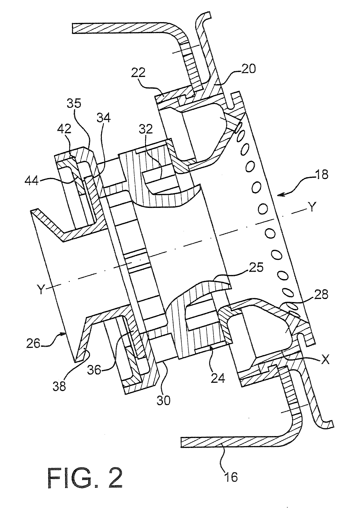
[0020] The inner chamber wall 8 and outer chamber wall 12 are united by a chamber base 16 at their upstream ends. A plurality of injection systems, typically fourteen to twenty-two, evenly spaced angularly (only one injection system has been shown in FIG. 1) are provided on the chamber base 16. As can be seen in greater detail in FIG. 2, each injection system 18 comprises a fixed part consisting of a ring 35 of a swirler element 24, a Venturi 25 a...


PUM


Abstract

Injection system of a turbojet engine. It comprises a fixed part and a sliding crossmember. The sliding crossmember comprises a flange capable of sliding on the sliding surface of the fixed part. The fixed part comprises antirotation means and the sliding crossmember of the complementary antirotation means to limit the rotation of the sliding crossmember relative to the fixed part. These means consist of at least one cutout formed in the flange and of at least one lug protruding into said at least one cutout of the flange of the sliding crossmember.

Description

BACKGROUND OF THE INVENTION [0001] 1. Technical Field [0002] The invention relates to a fuel injection system for a turbojet. More precisely, it relates to an injection system that comprises a fixed part and a sliding crossmember comprising a flange mounted so as to slide on a sliding surface of the fixed part of the injection system, the fixed part comprising antirotation means and the flange of the sliding crossmember comprising complementary antirotation means which interact with those of the fixed part to limit the rotation of the sliding crossmember relative to the fixed part. [0003] 2. Description of the Prior Art [0004] Turbojet combustion chambers comprise an inner wall and an outer wall connected at their upstream ends by an annular base to define an annular combustion chamber base. Injection systems evenly distributed over the periphery of the combustion chamber base deliver a mixture of air and fuel that is burnt to provide combustion gases. [0005] An injection system con...

Claims


Application Information

Patent Timeline
IPC IPC(8): F23R3/28
CPCY02T50/675F23R3/14Y02T50/60
Inventor BERNIER, DANIEL FRANCIS PAULLUNEL, ROMAIN NICOLASGASTON MARNAS, LAURENT PIERRE ELYSEE
Owner SN DETUDE & DE CONSTR DE MOTEURS DAVIATION S N E C M A
Why Eureka
Try Eureka