Lumber processing system

a processing system and lumber technology, applied in the field of lumber analysis, can solve the problems of large waste, low value of cut parts, and relatively high waste percentag

Inactive Publication Date: 2007-02-15
REMINGTON ARMS
View PDF8 Cites 8 Cited by
  • Summary
  • Abstract
  • Description
  • Claims
  • Application Information

AI Technical Summary

Benefits of technology

[0006] A lumber processing system constructed in accordance with the present invention accepts incoming marked lumber and produces cut parts of any of various, desired, predetermined shapes. The system broadly includes a scanning section, a computer section and a cutting section. Incoming lumber is scanned in the scanning section using two color cameras capturing images of both sides of the lumber first under normal lighting and second under ultraviolet (black) lighting for illumination of pre-marked defects. Images are processed in the computer section to produce a polygonal model of each section. These section models are then merged to produce a complete polygonal model of the entire scanned piece of lumber. A series of auxiliary packing computers review the complete model and each determine separate solutions for cutting the lumber to create the predetermined shapes. Parts are then ‘punched’ from the lumber in the cutting section utilizing high power lasers cutting from both sides of the lumber simultaneously. It should be noted that these parts, or blanks, are later worked to create a finished product, such as a gun stock.

Problems solved by technology

As a result, the placement of the blanks to be cut from each piece of lumber is time consuming and often results in great waste.
While each of these references represent some form of an advance in the state of the art of mass-production wood cutting and processing, they still result in relatively high percentages of waste, and thus lower the value of the cut parts than could be otherwise obtained.

Method used


Image

  • Lumber processing system
  • Lumber processing system
  • Lumber processing system

Examples


Embodiment Construction

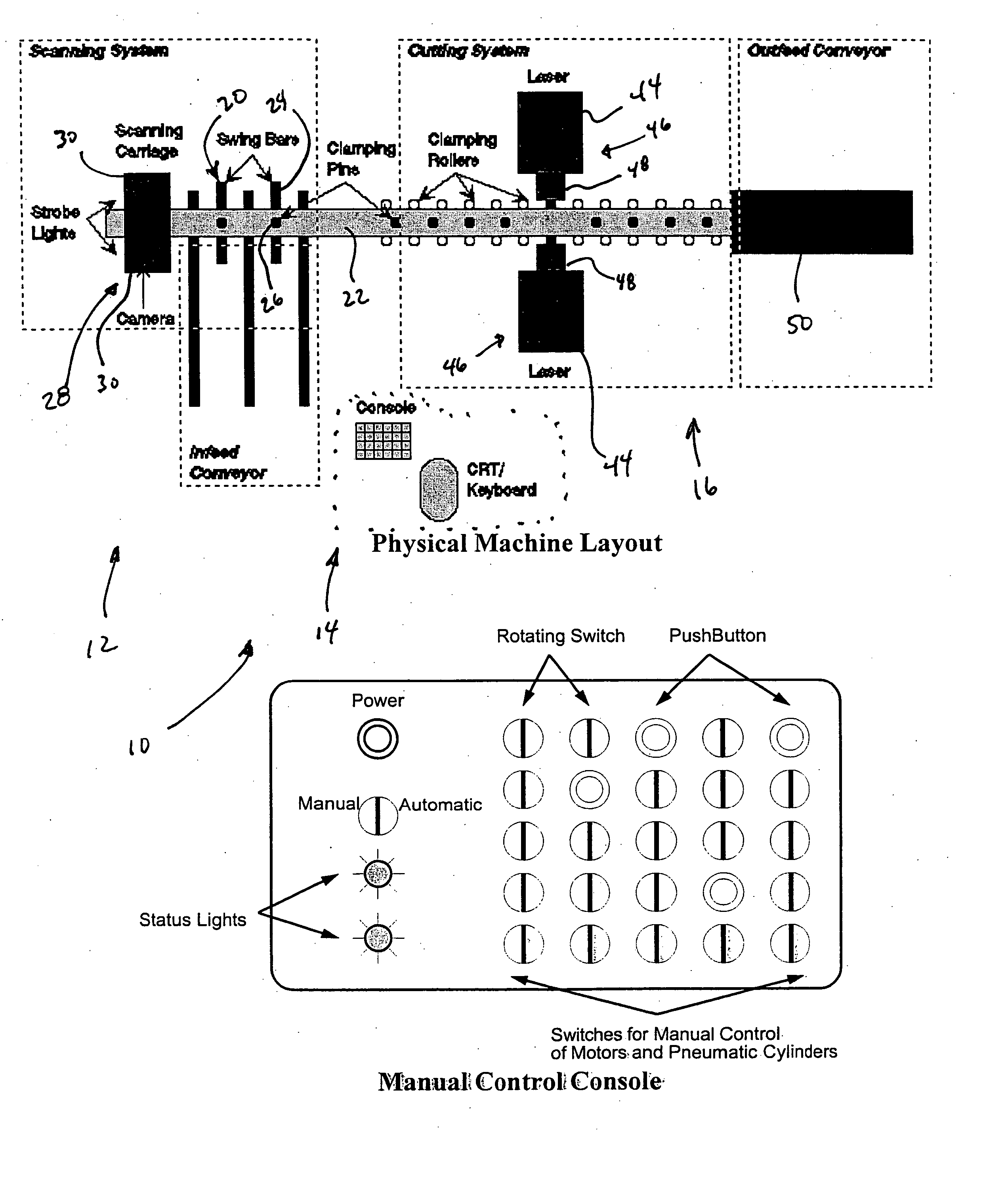
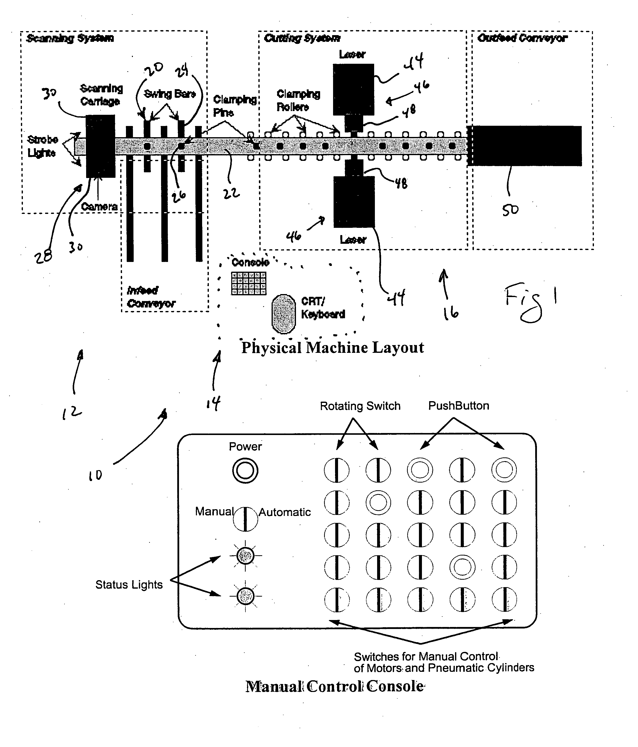
[0034] Referring now to the drawings, FIG. 1 depicts a preferred embodiment of a lumber processing system 10. The system 10 broadly includes a scanning section 12, a computer section 14, and a cutting and output section 16. Generally, the pieces of lumber configured for use in the system 10 are elongated and present a pair of opposed faces with a rectangular cross-sectional shape. For example, the piece of may have a 2″×10″ cross-sectional dimension. Of course, the system 10 may also accommodate lumber of various other dimensions.

[0035] The scanning section 12 includes an infeed conveyor 18 for receiving a piece of lumber. The infeed conveyor 18 transfers the lumber to a rotation station 20 along a central conveyor 22. The rotation station 20 uses a plurality of swing bars 24 to rotate the lumber from a flat, horizontal configuration to a vertical configuration where the faces of the lumber are generally vertical. A plurality of clamping pins 26 is provided to firmly support the lu...


PUM

PropertyMeasurementUnit
densityaaaaaaaaaa
coloraaaaaaaaaa
massaaaaaaaaaa

Abstract

A lumber processing system for cutting lumber into predetermined shapes broadly includes a scanning section, a computer section and a cutting section. Incoming lumber is scanned in the scanning section using two-color cameras capturing images first under normal lighting and second under ultraviolet (black) lighting for illumination of pre-marked defects. Images are processed in the computer section to produce a polygonal model of the lumber. A series of auxiliary packing computers review the model and determine separate solutions for cutting the lumber. Parts are then ‘punched’from the lumber in the cutting section utilizing high power lasers cutting from both sides of the lumber simultaneously.

Description

BACKGROUND OF THE INVENTION [0001] 1. Field of the Invention [0002] The present invention relates generally to a system for analyzing lumber and determining a preferred path for cutting the lumber. More particularly, the present invention relates to a system for cutting blanks from a piece of lumber where the lumber is analyzed and the blanks to be cut from the lumber are arranged to maximize the value of the cut parts from the lumber and minimize waste. [0003] 2. Discussion of the Prior Art [0004] Throughout history, the woodworking industry has continually strived to reduce the amount of waste in order to maximize profits and for environmental concerns, such as excessive deforestation and disposal of scrap lumber. Maximizing the utilization of lumber has met with numerous challenges in an increasingly industrialized world. For example, each piece of lumber is unique having its own shape, density, color, and defects. In the more industrialized sectors of the woodworking industry wh...

Claims


Application Information

Patent Timeline
Patent Type & Authority Applications(United States)
IPC IPC(8): B27C9/00B27M3/00B27M1/08B23Q15/00B27L9/00B23Q16/00B27L3/00B27L5/00
CPCB23D59/008B23K26/03B23K26/032B23K26/0617G06Q10/043B23K26/4045B27G1/00B27M1/06B23K26/0823B23K2103/36B23K2103/50
Inventor ZIELKE, GREGMOODY, JOHN
Owner REMINGTON ARMS
Why Eureka
Try Eureka