Impact tool

a technology of impact tool and axial direction, which is applied in the direction of percussive tool, manufacturing tool, portable drilling machine, etc., can solve the problems of generating a large amount of noise, affecting the axial direction of both members, and affecting the relative movement of both members, so as to reduce the noise without lowering the ability of screw tightening

Inactive Publication Date: 2007-02-15
HITACHI KOKI CO LTD
View PDF13 Cites 31 Cited by
  • Summary
  • Abstract
  • Description
  • Claims
  • Application Information

AI Technical Summary

Benefits of technology

[0016] The present invention, considering the above-mentioned problem, has an object to

Problems solved by technology

However, because the impact tool has a rotary blow mechanism that generates a rotary blow force, it is a problem that there is a lot of noise while working.
However, because the hammer 8 also performs a back-and-forth movement along with a rotary movement during works using such a rotary blow tool, these movements become a source of vibration, and the wood 12, a fastening object, is excited to an axial direction through an anvil 3, the tip tool 4 and the screw 11, thereby generating a large amount of noise.
However, if the torque is hanged on- the torque transfer unit, a big friction force is generated, and by this friction force, the relative movement toward the axial direction of both members is obstructed.
Hence, it was difficult to reduce the axial force applied on the tip tool or the screw, so the noise reduction effect

Method used


Image

  • Impact tool
  • Impact tool
  • Impact tool

Examples


first embodiment

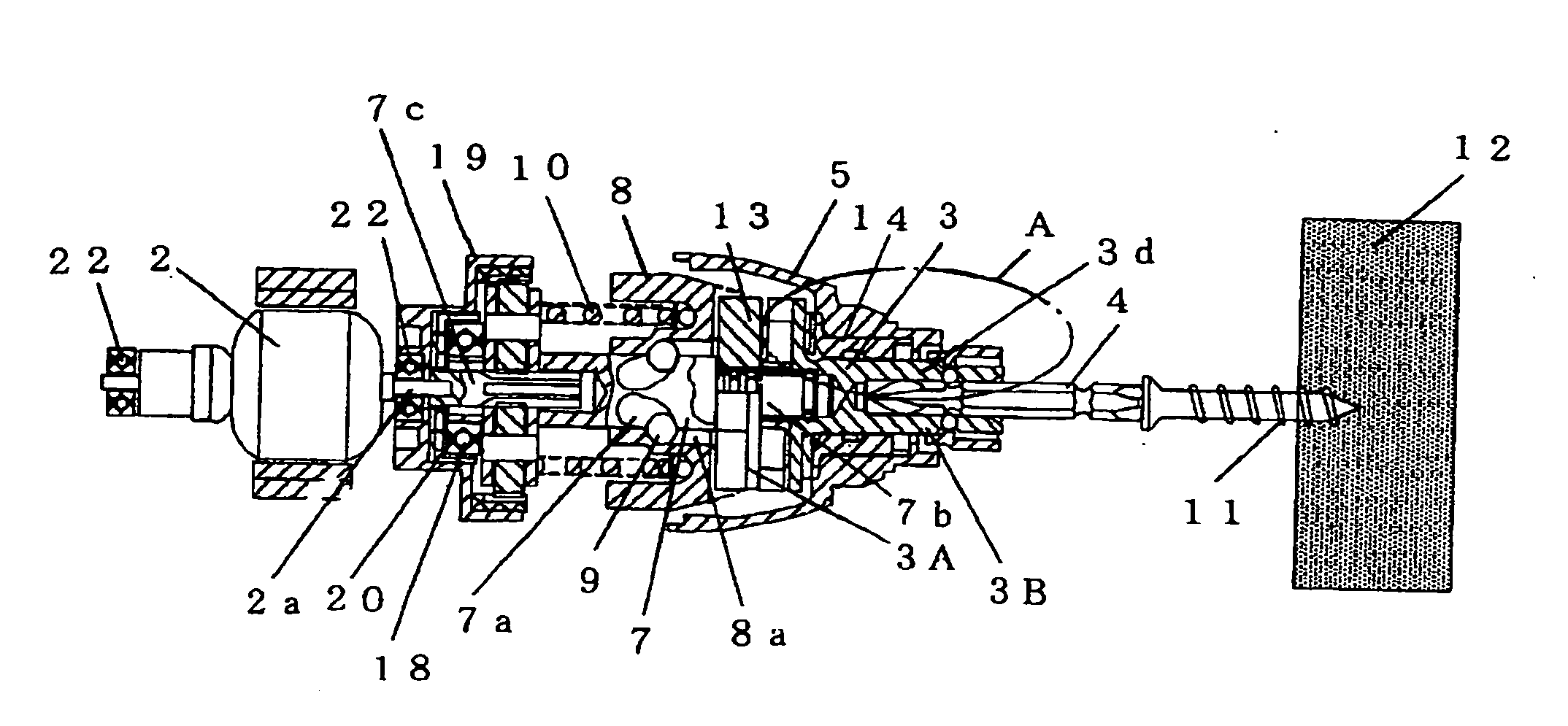
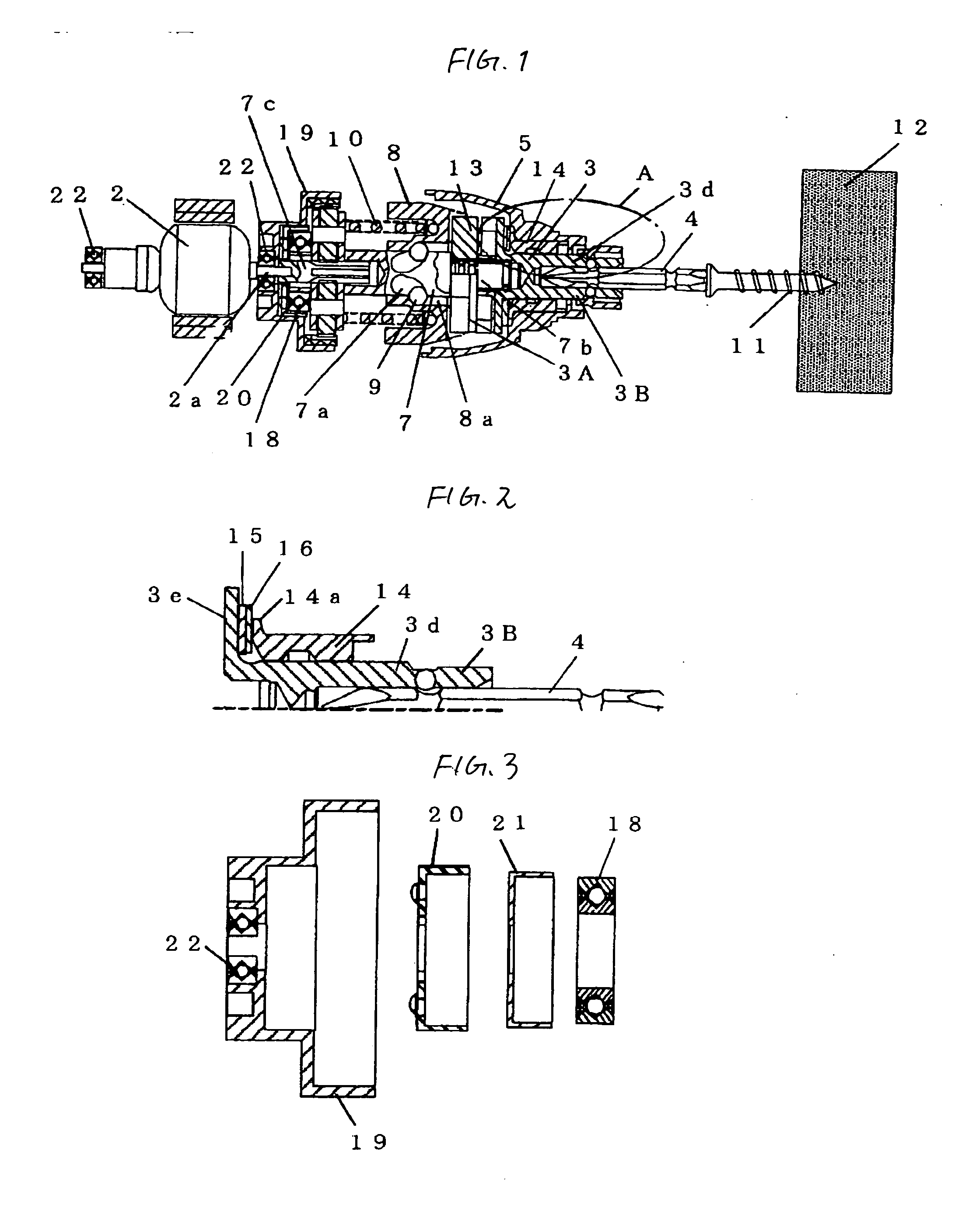
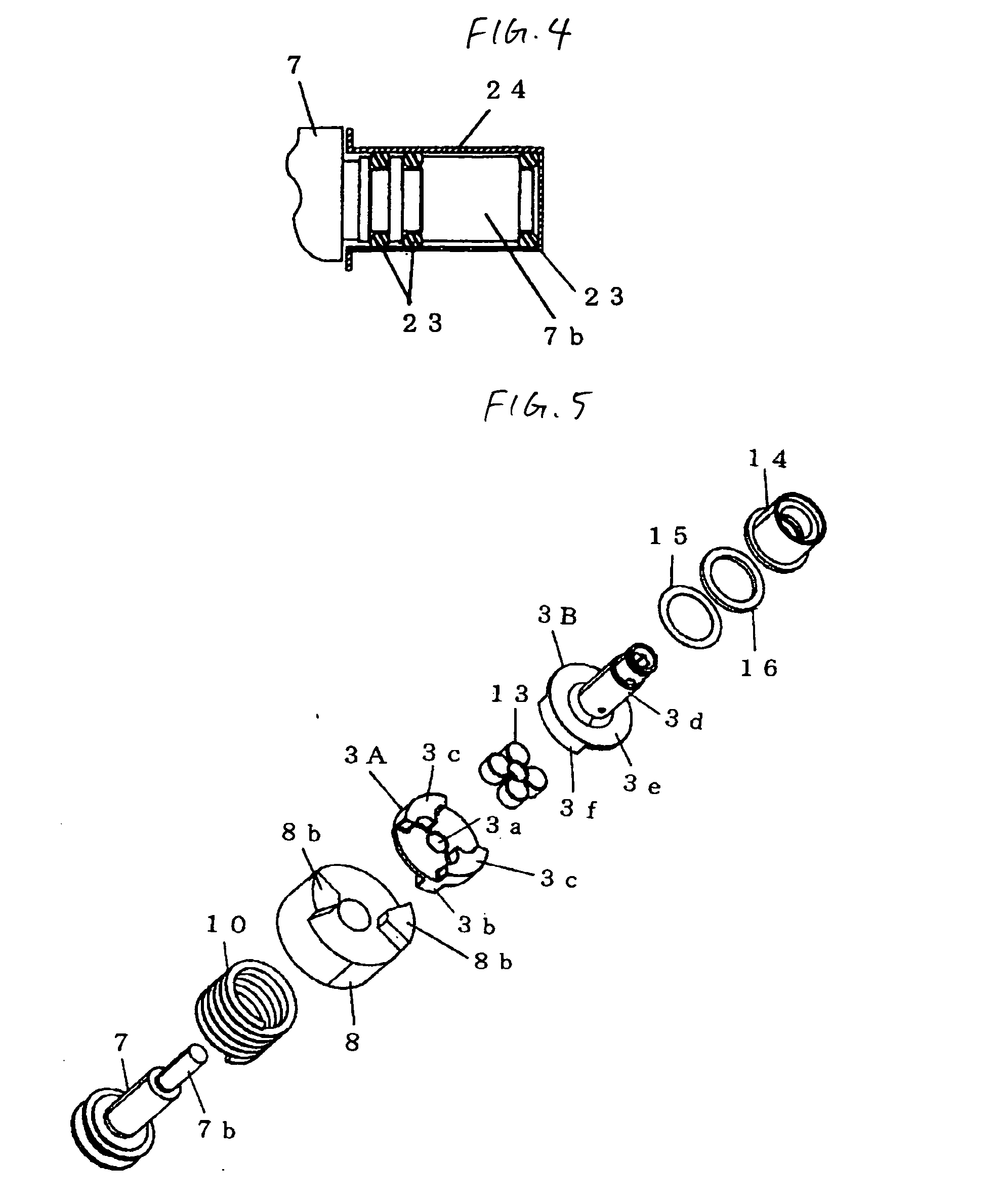
[0059] Later, as the same movement is repeated, the rotary blow force is intermittently transferred from the tip tool 4 to the screw 11, and the screw 11 is screwed in the wood, the fastening object. Also, in the impact tool because the damping mechanism completes the damping function for both the rotation direction and the axial direction, the axial vibration and the rotary vibration by the blow force are absorbed by the damping mechanism, but because the spring constant value to the axial direction is set to be lower than the spring constant value to the rotation direction, the transfer from the rotary blow mechanism to especially the wood of the vibration to the axial direction is restricted, whereby the noise is reduced.

[0060] Also, since the spring constant value in the rotation direction of the rubber damper 13 is set higher than the value of the axial direction, the rubber damper 13 can transfer the large rotary torque from the rotary blow mechanism. Also, on the rotary torq...

second embodiment

[0074] Also, in the impact tool in accordance with the second embodiment, the spring constant value in the rotation direction of the rubber damper 17 is set to be high than the value in the axial direction and the rubber damper 17 completes the damping function for both the rotation direction and axial direction. In this case, since the spring constant value to the axial direction of the rubber damper 17 is set to be lower than the spring constant value in the rotation direction, the spread from the rotary blow mechanism, the vibration source, especially to the wood of the vibration in the axial direction, is restricted, whereby the noise is reduced.

[0075] Further, since the spring constant value in the rotation direction of the rubber damper 17 is set to be higher than the value in the axial direction, the rubber damper 17 can transfer a high rotary torque from the rotary blow mechanism. Also, the damping mechanism makes the split piece 4a of the tip tool 4 directly contact the paw...


PUM

PropertyMeasurementUnit
Forceaaaaaaaaaa
Circumferenceaaaaaaaaaa
Noiseaaaaaaaaaa

Abstract

An impact tool for reducing noise without lowering the tightening ability. The impact tool gives a rotary blow force to a tip tool by mounting a rotary blow mechanism on a spindle rotatably driven by a motor and intermittently transferring the rotary blow force generated by the rotary blow mechanism from a hammer to the tip tool via an anvil, damping materials absorbing at least the vibration in the radial direction are arranged on at least one side of both supports of the axial direction of the spindle 7. The damping material is interposed between a bearing that rotatably supports the rear end portion of the spindle and an inner cover that holds the same, and an O-ring is interposed as a damping material between the front end portion of the spindle and an anvil that rotatably supports the same.

Description

BACKGROUND OF THE INVENTION [0001] The present invention relates to an impact tool for doing necessary works such as tightening a screw and others by generating a rotary blow force, especially to an impact tool that reduces noise. [0002] While rotating a tip tool by generating a rotary blow force using a motor as a driving source, an impact tool as a form of an electric tool intermittently gives a rotary blow force to the tip tool to do some works such as tightening a screw and others, but because of characteristics such as little counteraction, high tightening ability, and others, the impact tool has been widely used. However, because the impact tool has a rotary blow mechanism that generates a rotary blow force, it is a problem that there is a lot of noise while working. [0003]FIG. 17 shows a longitudinal section of a general impact tool that has been conventionally used. [0004] The conventional impact tool shown in FIG. 17 uses a battery pack 1 as a power source, drives a rotary ...

Claims


Application Information

Patent Timeline
IPC IPC(8): B25D17/24
CPCB25B21/02B25D17/24B25D17/11B25D11/068
Inventor MURAKAMI, TAKUHIROKAMIMURA, JUNICHIOOMORI, KATSUHIROOHTSU, SHINKIINAGAWA, HIROTOWATANABE, HIDEKI
Owner HITACHI KOKI CO LTD
Why Eureka
Try Eureka