
Cutter unit of stapler

a stapler and cutter technology, applied in the field of staplers, can solve the problems of increasing part cost or product cost, operational hazards, and the inability to bend the staple leg in a stable shape, and achieve the effect of increasing the inclination angle of the chu

Inactive Publication Date: 2007-02-15
MAX CO LTD
View PDF8 Cites 14 Cited by
  • Summary
  • Abstract
  • Description
  • Claims
  • Application Information

AI Technical Summary

Benefits of technology

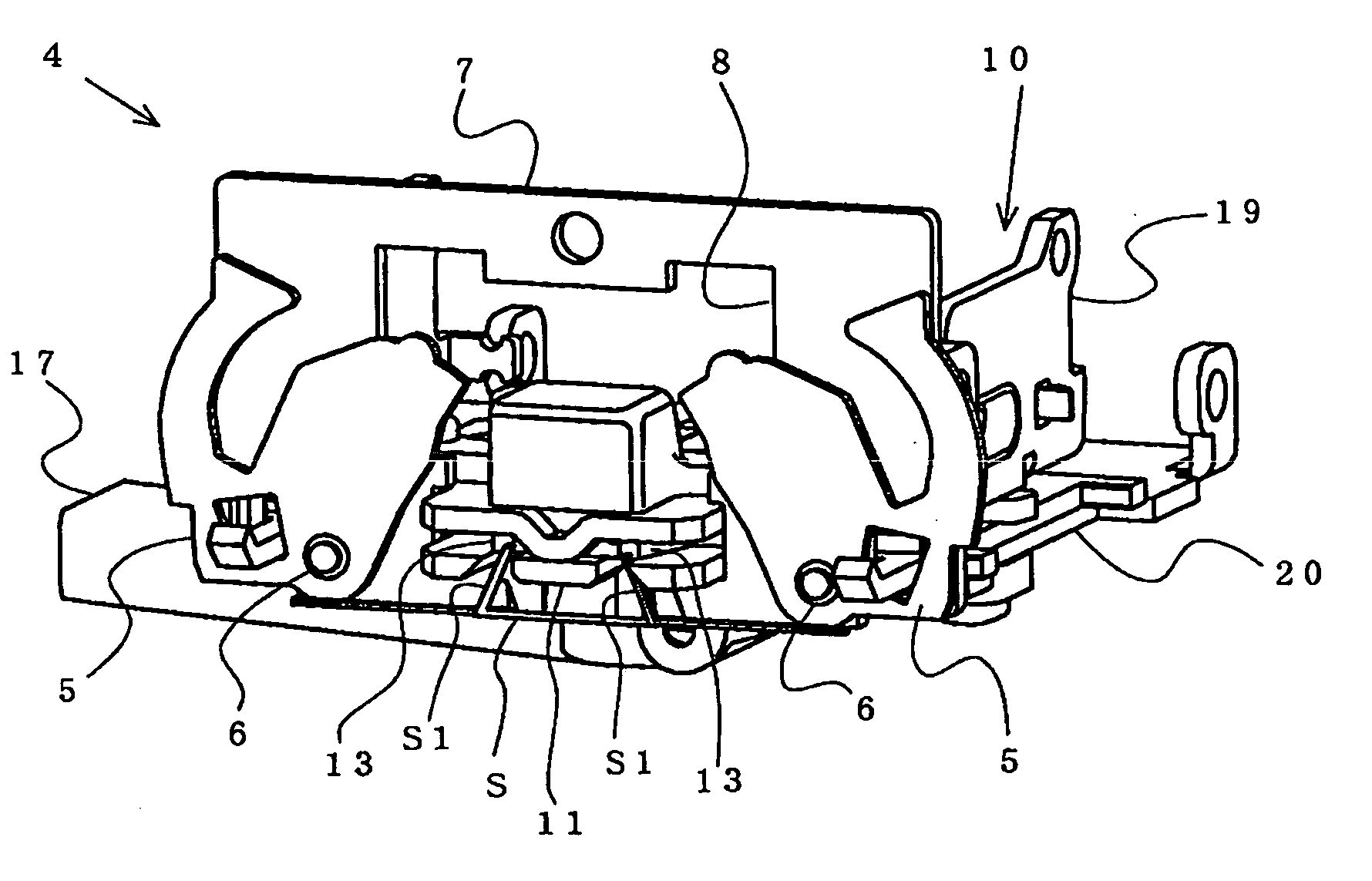
[0016] According to the invention, the front end portion of the staple leg is cut by arranging the fixed cutter between the staple legs and operating the movable cutter from the outer side to the inner side of the staple leg and therefore, in a state of binding the staple, a burr formed at a cutting face of the staple leg is formed to direct to an inner side of the staple leg, that is, to a side of a face of the sheet to be bound, the sheet is bound in a state in which the burr at a front end face of the staple leg is brought into close contact with a side of a back face of the sheet to be bound, even when the hand is brought into contact with the staple leg, the hand is not brought into contact with the burr and there is not a concern of being injured by the burr produced by cutting the staple leg.
[0017] Further, the cutter unit is arranged movably between a position opposed to the staple strike out portion constituting the operation region to pivot the movable clincher and a position escaped from the operation region to pivot the movable clincher, in a state of advancing the cutter unit between the movable clinchers pivoted to the standby positions, the staple leg penetrated through the sheet to be bound is cut by the cutter unit, after escaping the cutter unit from the operation region of the movable clincher, the staple leg cut by the movable clincher is bent and therefore, a length of a portion of the movable clincher engaged with the staple leg can be formed to be large, and an excellent binding shape can be provided by engaging the movable clincher with a front end portion of the staple leg.
[0020] According to the invention, the cutting chip of the staple leg is discharged to the chute formed on the side of the lower face of the cutter unit by way of the opening formed at the cutter unit, guided into the chip containing portion by way of the chute and is stored in the chip containing portion and therefore, it can be prevented that the cutting chip of the staple leg cut by the cutter unit advances to a drive mechanism or the like or a clearance of a part of the stapler to bring about an operational hazard or the like in the drive mechanism or the like. Further, the cutter unit for cutting the staple leg is arranged to be able to slide to move between a staple strike out position and an escaping position on a rear side of the position, the cutting chip is discharged to a side of the lower face of the support base by way of openings formed at the cutter unit and the support base and therefore, even when a stapler main body is installed in a horizontal direction or a vertical direction to bind the sheet to be bound arranged in the horizontal direction and the vertical direction, the cutting chip can be guided to be discharged into the chip containing portion by way of the chute and the stapler can be included in various kinds of copiers or the like to bind the sheet to be bound arranged in the horizontal direction and the vertical direction.
[0021] Further, the one end side of the chute is supported pivotably by the side of the lower face of the support base slidably supporting the cutter unit, the other end side of the chute is arranged in the chip containing portion, the cutting chip is discharged into the chip containing portion by pivoting the chute to thereby increase the inclination angle of the chute by operating to pivot the clincher mechanism portion and therefore, the cutting chip can firmly be discharged into the chip containing portion and the cutting chip stays in the chute without being scattered into the stapler main body.

Problems solved by technology

However, according to the mechanism of cutting the staple leg by the above-described movable clincher, respectives of a pair of the movable clinchers are axially supported and supported to be able to pivot, in order to cut the staple leg between the movable cutter edge and the fixed cutter edge of two pieces of the movable clinchers, a high dimensional accuracy is requested for setting a clearance amount or the like between the two cutter edges and therefore, there poses a problem that accuracies are requested in part dimensions, working, integrating or the like, part cost or product cost is increased, further, there is brought about an operational hazard of a failure in cutting, a failure in clinching or the like by wear or the like.
Further, a direction of a burr formed at an end face of the staple leg after cutting is formed to an outer side of the staple leg and therefore, there is a concern of being injured by being brought into contact with the staple after binding the staple.
Further, according to the latter of the background art in which the movable cutting member is provided on the lower side of the movable clincher, and the staple leg is cut between the movable cutting member and the fixed cutting member by moving the movable cutting member in the direction substantially orthogonal to the direction of penetrating the staple leg, the movable clincher and the movable cutting member need to be arranged on the same plane and therefore, a length of a portion of the movable clincher engaged with the staple leg cannot be formed to be large and therefore, there poses a problem that a shape of clinching the staple leg cannot be bent in a stable shape.
Further, a direction of a burr formed in cutting at a cut end portion of the staple leg is formed in a direction of a side face of the staple and therefore, there is a concern of being injured by being brought into contact with the staple after binding the staple.
Further, according to the stapler having the above-described cutter unit, there may be posed a problem that a cutting chip cut by the cutter unit is scattered at inside of the stapler to be pinched by an operating mechanism of a drive gear, a link or the like to bring about an operational hazard, or dropped onto a circuit board for control to shortcircuit to destruct the circuit.
However, according to the above-described cutting chip processing apparatus of the staple leg, the chute mounted to the cutting chip discharging portion of the cutter unit is mounted to a front side of the stapler, further, the lower end opening portion of the chute is closed by the gravitational force operation and therefore, for example, when the stapler is installed to direct to the vertical direction to bind sheets to be bound substantially in a vertical state, the cutting chip is not discharged into the chute, further, the lower end opening portion is not opened or closed and therefore, the stapler cannot be installed to direct in a number of directions and the stapler needs to be designed newly.

Method used


Image

  • Cutter unit of stapler
  • Cutter unit of stapler
  • Cutter unit of stapler

Examples


Embodiment Construction

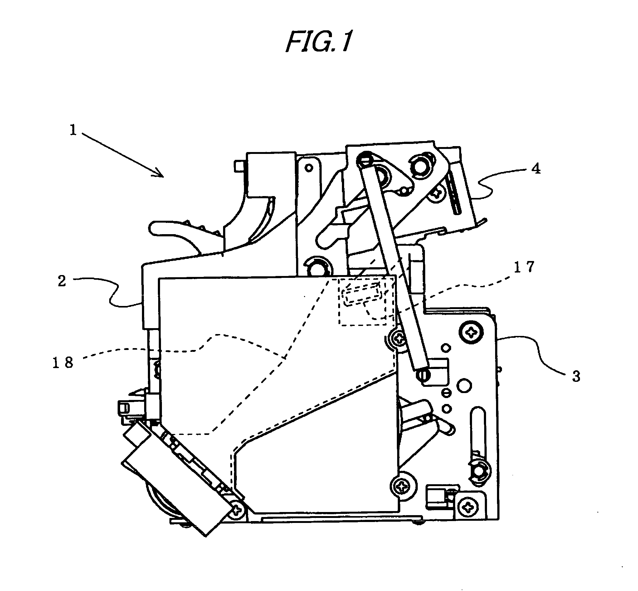
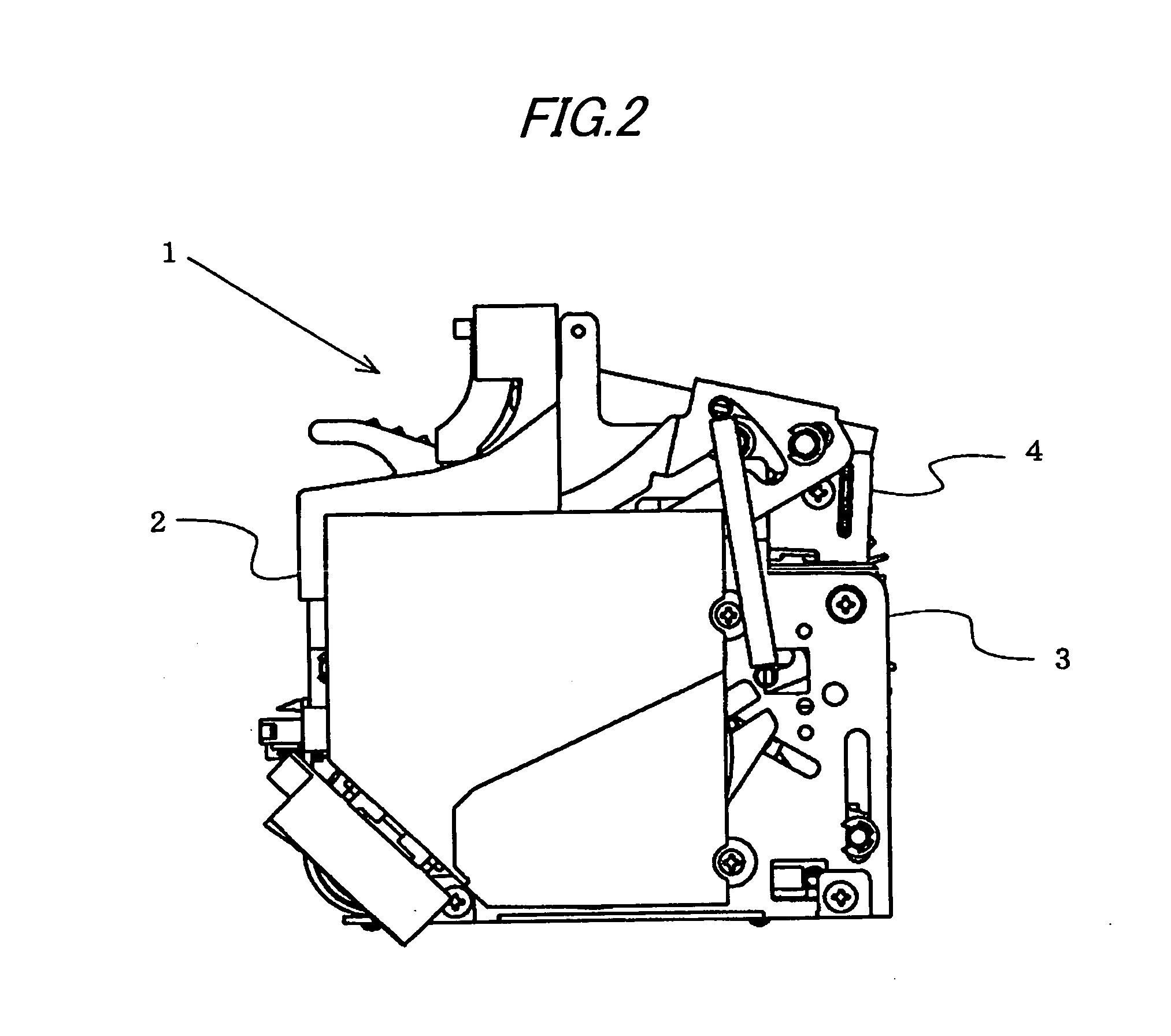
[0048]FIG. 1 is a stapler embodying a cutter unit according to a first exemplary embodiment of the invention, inside of a machine frame 2 forming an outer contour of the stapler 1 is contained with an electric motor and a drive mechanism driven to rotate by the electric motor, further, a lower portion of the machine frame 2 is formed with the striking mechanism portion 3 driven by the drive mechanism for striking out a staple formed in a C-shape to sheets to be bound. The striking mechanism portion 3 of the stapler 1 according to the embodiment is constituted to form a number of staple members in a straight shape connected with each other into the staples in the C-shape by forming means and striking out the formed staples upwardly to sheets to be bound arranged on an upper side of the striking mechanism portion 3 by strike out means. Further, an upper portion of the machine frame 2 opposed to the striking mechanism portion 3 is formed with the clincher mechanism portion 4 for foldin...


PUM


Abstract

A cutter unit 10 with a fixed cutter 11 arranged between staple legs and a movable cutter 13 operated from an outer side to an inner side of the staple leg is provided. The cutter unit 10 is arranged slidably between a position advanced into an operation region a movable clincher 5 and a position escaped from the operation region of the movable clincher 5. The cutter unit 10 is advanced to a staple strike out portion to cut the staple leg penetrated through a sheet to be bound, the cutter unit 10 is escaped from the operation region of the movable clincher 5 and thereafter, the staple leg is bent by operating to pivot the movable clincher 5.

Description

TECHNICAL FIELD [0001] The present invention relates to a stapler for striking out a staple formed in a C-shape to a sheet to be bound and folding to bend staple legs penetrated to a back face side of the sheet to be bound along the back face of the sheet to be bound, particularly relates to a cutter unit of a staple leg for cutting a leg portion of a staple penetrated to a back face side of a sheet to be bound in accordance with a thickness of the sheet to be bound. [0002] Further, the invention relates to a processing apparatus for processing a cutting chip of a stable leg cut by the cutter unit. BACKGROUND ART [0003] Normally, in a staple for bundling to bind a plurality of sheets to be bound, there are prepared a number of kinds of staples with different leg lengths thereof in correspondence with a number of sheets to be bound, and a staple with a leg length in accordance with a thickness of the sheets to be bound is charged to a stapler to be used. However, when the thickness o...

Claims


Application Information

Patent Timeline
Patent Type & Authority Applications(United States)
IPC IPC(8): B25C5/02B27F7/19
CPCB27F7/19B27F7/36B27F7/23
Inventor SHIMIZU, TOSHIOKISHI, KAZUHIKOHIGUCHI, KAZUO
Owner MAX CO LTD
Learn More