Movable body position control device and stage device using the movable body position control device

Inactive Publication Date: 2007-02-15
SUMITOMO HEAVY IND LTD
View PDF6 Cites 9 Cited by
  • Summary
  • Abstract
  • Description
  • Claims
  • Application Information

AI Technical Summary

Benefits of technology

[0013] Accordingly, embodiments of the present invention can provide a novel and useful movable body position control device and stage device using the movable body position control device, in which one or more of the problems described above are eliminated.
[0014] More specifically, the embodiments of the present invention can provide a movable body position control device and stage device using the movable body position control device whereby a driving force can be generated so that a difference in translational actions of a movable body can be prevented.
[0015] The embodiments of the present invention can also provide a movable body position control device including a pair of position detectors configured to detect moving positions of both ends of a movable body; a pair of driving parts, the driving parts being configured to drive the both ends of the movable body based on a detection signal from the pair of the position detectors; a translation control part configured to make the driving parts can generate a driving force whereby a difference of translational action of the movable body can be prevented in a case where a moving speed of the movable body is changed due to a disturbance, and configured to control the driving parts so that detected positions of the position detectors can be consistent with each other; and a rotation control part configured to make the driving parts can generate the driving force whereby a rotational action of the movable body can be prevented in a case where the moving speed of the movable body is changed due to the disturbance and the movable body is displaced in a rotational direction, and configured to control the driving parts so that the moving body does not lean against a moving direction.
[0016] The embodiments of the present invention can also provide a stage device, including: a fixed base; a stage movably provided against the fixed base and extending in a direction perpendicular to a moving direction; a guide part configured to guide both ends of the stage in the moving direction; a pair of driving parts configured to give a driving force to the both ends of the stage; a pair of position detectors configured to detect moving positions of the both ends of the stage; and a control part configured to control the driving parts so that the stage can move at a designated speed; wherein the control part can include a translation control part configured to make the driving parts can generate a driving force whereby a difference of translation actions of the stage can be prevented in a case where a moving speed of the stage is changed due to a disturbance, and configured to control the driving parts so that detected positions of the position detectors are consistent with each other; and a rotation control part configured to make the driving parts can generate a driving force whereby a rotational action of the stage can be prevented in a case where the moving speed of the stage is changed due to the disturbance and the stage is displaced in a rotational direction, and configured to control the driving parts so that the stage does not lean against a moving direction.
[0017] According to the above-mentioned movable body position control device and stage device using the movable body position control device, a driving force can be generated so that a difference of translational actions of a movable body can be prevented.

Problems solved by technology

Therefore, the disturbance is not always input to the both end parts of the movable body.
In a case where such a disturbance is input, it is difficult to stabilize the moving speed that is changed due to the disturbance at a moment by the feed back control.
Therefore, it is difficult to make highly precise movements of the movable body to achieve such as film thickness precision applied by the coating nozzle or sensing precision of the sensor.

Method used


Image

  • Movable body position control device and stage device using the movable body position control device
  • Movable body position control device and stage device using the movable body position control device
  • Movable body position control device and stage device using the movable body position control device

Examples


Embodiment Construction

[0025] A description will now be given, with reference to FIG. 1 through FIG. 6, of embodiments of the present invention.

[First example of the present invention]

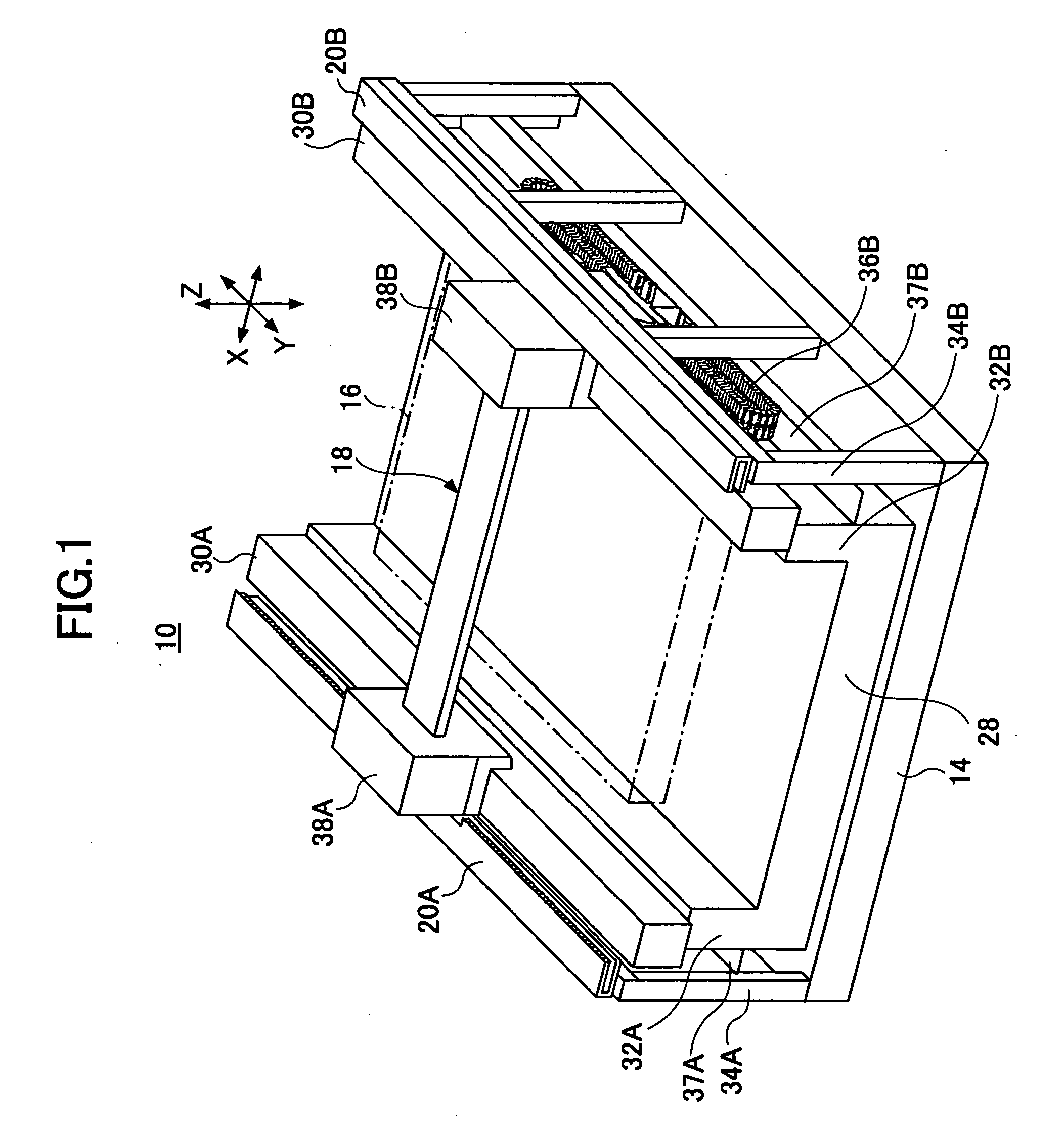
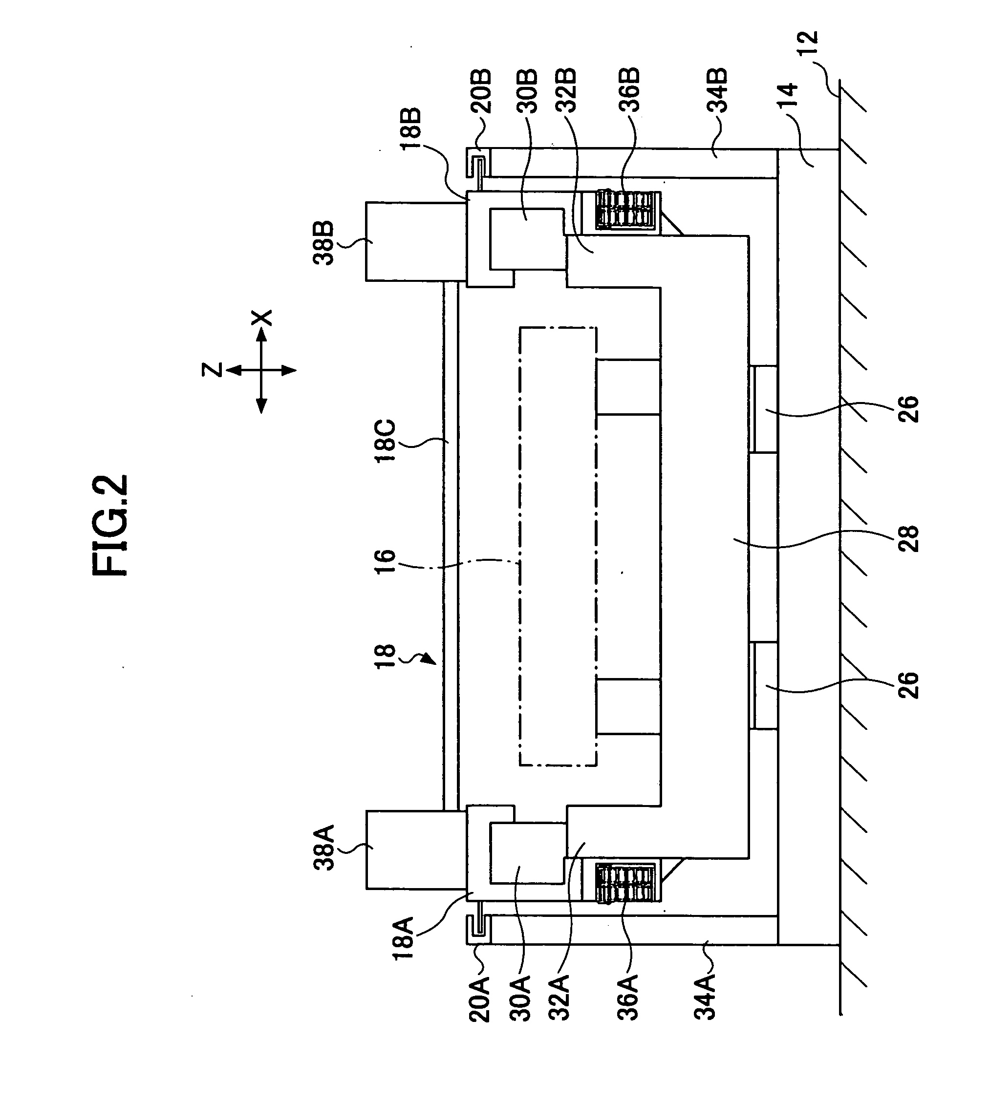
[0026]FIG. 1 is a perspective view of a stage device where a movable body position control device of an embodiment of the present invention is applied. FIG. 2 is a front view of the stage device shown in FIG. 1. FIG. 3 is an enlarged front view of a structure of a linear motor 20B and a guide part 30B. FIG. 4 is an enlarged plan view of the structure of the linear motor 20B and the guide part 30B.

[0027] As shown in FIG. 1 through FIG. 4, a stage device 10 is a gantry moving type stage. The stage device 10 includes a fixed base 14, a substrate table 16, a movable stage 18, a pair of linear motors 20A and 20B (See FIG. 2) as a driving part, and linear scales 22A and 22B (See FIG. 3) as a position detector. The fixed base 14 is fixed on a concrete base 12. The substrate table 16 is supported on the fixed base 14. The movable...


PUM


Abstract

A movable body position control device includes a pair of position detectors configured to detect moving positions of both ends of a movable body; a pair of driving parts, the driving parts being configured to drive the both ends of the movable body based on a detection signal from the pair of the position detectors; a translation control part configured to make the driving parts can generate a driving force whereby a difference of translational action of the movable body can be prevented in a case where a moving speed of the movable body is changed due to a disturbance, and configured to control the driving parts so that detected positions of the position detectors can be consistent with each other; and a rotation control part configured to make the driving parts can generate the driving force whereby a rotational action of the movable body can be prevented in a case where the moving speed of the movable body is changed due to the disturbance and the movable body is displaced in a rotational direction, and configured to control the driving parts so that the moving body does not lean against a moving direction.

Description

CROSS-REFERENCE TO RELATED APPLICATION [0001] This application is a U.S. continuation application filed under 35 USC 111(a) claiming benefit under 35 USC 120 and 365(c) of PCT application JP05 / 008367, filed May 6, 2005, which claims priority to Application Ser. No. 2004-149651, filed in Japan on May 19, 2004. The foregoing applications are hereby incorporated herein by reference. BACKGROUND OF THE INVENTION [0002] 1. Field of the Invention [0003] The present invention generally relates to movable body position control devices and stage devices using the movable body position control devices. More particularly, the present invention relates to a movable body position control device and stage device using the movable body position control device whereby rotational action of a movable body and change of a moving speed due to disturbance when both ends of the movable body (stage) are translated in a single direction are prevented. [0004] 2. Description of the Related Art [0005] Movable ...

Claims


Application Information

Patent Timeline
IPC IPC(8): G05B19/18G05B13/00B23Q1/58G05B19/19G05D3/00H02P5/74
CPCG05B19/19G05B2219/50228G05B2219/41369G05B2219/41368G05D3/00
Inventor SAKO, DAISUKE
Owner SUMITOMO HEAVY IND LTD
Why Eureka
Try Eureka