Two-panel liquid crystal system with circular polarization and polarizer glasses suitable for three dimensional imaging

Inactive Publication Date: 2007-02-15
VIRRILLI JAMES
View PDF13 Cites 88 Cited by
  • Summary
  • Abstract
  • Description
  • Claims
  • Application Information

AI Technical Summary

Benefits of technology

[0009] Further, it is an object of the present invention to provide three-dimensional imaging systems and methods that can be readily adapted for use with standard computing systems and polarization glasses.
[0010] Additionally, it is an object of the present invention to provide three-dimensional imaging systems and methods that operate without constraining the viewer with respect to range of movement.
[0011] It is also an object of the present invention to provide three-dimensional imaging systems and methods that can operate as an “add-on” to conventional computing displays and personal computers.
[0013] According to one or more embodiments, two LC panels are provided, with the two panels being stacked one in front of the other relative to a light source. According to these embodiments, the first, or back, LC panel is arranged closest to the light source and with a polarizer placed on its front and rear side in the manner of a typical liquid crystal display (“LCD”). This back LC panel arrangement is driven by an appropriate control system, such as software running on a computer processor and control board, to generate a composite image that is a derivative of two stereopair images that need to be viewed separately by the left and right eye of the viewer in order to create the perception of a three-dimensional image. The stereopair images may, for example, be from a database of stereo images, be received from a feed from two camera sources, be the result of computer rendering or simulation programs, or the like. The light emitted by the back panel and the polarizers is polarized thus emerges from this trio at a certain, known angle. This light is then thereafter rotated, on a pixel by pixel basis, to a desired polarization by the second LC panel. The viewer thus wears polarized glasses that transmit light polarized at different angles to the left and right eye, preferably with the lens for each eye having an orthogonal polarization angle relative to the other to achieve best image separation. By controlling the angle of polarization of light exiting the front LC panel in accord with the known polarization characteristics of the eyeglasses, the present invention is able to control the intensity of light directed to each eye and hence the image perceived by each eye. Using an appropriate algorithm according to the present invention to calculate the angle of polarization, one of a stereopair images are delivered to each eye to create the perception of three dimensional images.

Problems solved by technology

However, these types of systems result in eyestrain associated with the “flicker” created by the shutter.
While disclosing a highly effective imaging system, however, Putilin et al. describes a highly complex system that requires significant power.
Thus, it may not be suitable for all purposes, including low cost applications where low-tech and flexible options are desirable.

Method used


Image

  • Two-panel liquid crystal system with circular polarization and polarizer glasses suitable for three dimensional imaging
  • Two-panel liquid crystal system with circular polarization and polarizer glasses suitable for three dimensional imaging
  • Two-panel liquid crystal system with circular polarization and polarizer glasses suitable for three dimensional imaging

Examples


Embodiment Construction

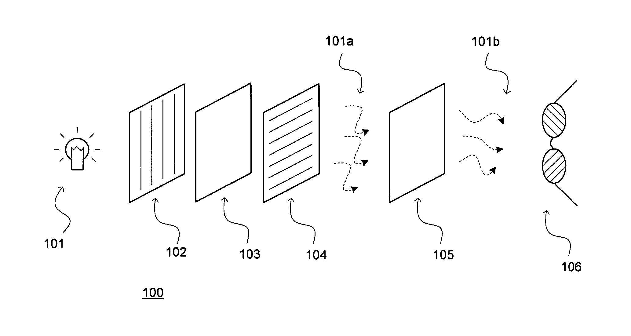
[0026] Referring to the drawings and first to FIG. 1, one or more embodiments of the invention relate to the combination of a first polarizer 102 (or “back polarizer”), a back LC panel 103, a second polarizer 104 (or “front polarizer”), a front LC panel 105 and polarizing glasses 106. These elements, as depicted, are arranged in a stacked configuration. The first polarizer 102 is situated immediately in front of a suitable light source 101 such that light will be transmitted through the first polarizer 102, then through the back LC panel 103 (where its polarization can be changed as described below), then through the second polarizer 104. As will be readily appreciated by one skilled in the art, the polarization rotation imparted by the individual pixels of the back LC panel 103 cooperate with the second polarizer 104 to produce polarized light 101a having an intensity profile representative of an image that depends upon how the individual pixels of back LC panel 103 are controlled....


PUM


Abstract

Disclosed herein are systems and methods for three dimensional display that produce stereo images (left and right eye images) each having particular known polarization so that they can be segregated and viewed with suitable polarizer eyeglasses to create the perception in the human mind of a three-dimensional image. According to one or more embodiments, two liquid crystal panels are utilized with the two panels being stacked one in front of the other relative to a light source and two polarizers are used surrounding the panel closest to the light source. In alternative embodiments, that panel and polarizers comprise a typical liquid crystal display (“LCD”) monitor. In preferred embodiments, images produced by the system are then circularly polarized for decoding by eyeglasses having corresponding circularly polarized lenses.

Description

CROSS-REFERENCE TO RELATED APPLICATIONS [0001] This application claims the benefit of the filing dates of prior U.S. Provisional Patent Applications Ser. Nos. 60 / 697,540, filed Jul. 11, 2005, and 60 / 741,079, filed Dec. 1, 2005.FIELD OF THE INVENTION [0002] This invention relates generally to three-dimensional imaging. More specifically, the present invention relates to three-dimensional imaging using a dual-layered liquid crystal arrangement combined with polarizer eyeglasses. BACKGROUND OF THE INVENTION [0003] Objects are seen in three dimensions because light reflects from them and generates a light field in space. The two eyes of a viewer perceive this light field differently due to their different locations in space relative to the object, and the brain of the viewer processes the different perceptions of the light field by the two eyes to generate three-dimensional (“3-D”) perception. [0004] Stereoscopic imaging is a technique utilized to simulate three-dimensional images to vi...

Claims


Application Information

Patent Timeline
IPC IPC(8): G02B27/22G02B30/25
CPCG02B27/2228H04N13/0434G02C7/12G02B30/34H04N13/337G02F1/1335H04N13/00
Inventor MATVEEV, ALEXANDERTISHUTIN, OLEGKANASHIN, KONSTANTIN
Owner VIRRILLI JAMES
Why Eureka
Try Eureka