

Electromagnetic-wave-shielding light-transmitting window member and method for producing the same
a technology of electromagnetic shielding and light-transmitting window, which is applied in the direction of magnetic/electric field screening, resistive material coating, synthetic resin layered products, etc., can solve the problems of electromagnetic waves that may have adverse effects on the human body, electromagnetic waves are being investigated, and it is extremely difficult to produce coarse meshes using thin fibers
Inactive Publication Date: 2007-02-15
BRIDGESTONE CORP
View PDF5 Cites 15 Cited by
- Summary
- Abstract
- Description
- Claims
- Application Information
AI Technical Summary
Benefits of technology
[0020] Objects of the present invention are to provide a method for producing an electromagnetic-wave-shielding light-transmitting window member in which a printing paste is cured by irradiation of ultraviolet light, thus eliminating the problems of dripping during heating and tact time, and in which the blending amount of particles of an electroless pla
Problems solved by technology
In recent years, along with widespread use of OA equipment, communications equipment, and the like, problems associated with electromagnetic waves generated from such equipment have been receiving attention.
There have been concerns that electromagnetic waves may have adverse effects on the human body, and also there have been occurrences of malfunction and the like of precision equipment caused by electromagnetic waves.
The reason for this is that although a coarse mesh can be produced with thick fibers, it is extremely difficult to produce a coarse mesh using thin fibers.
Accordingly, known electromagnetic-wave-shielding light-transmitting window members including such conductive meshes have a light transmittance of at most about 70%, and thus it is not possible to achieve satisfactory light transmittance, which is disadvantageous.
Furthermore, the known conductive meshes readily cause moire fringes (interference fringes) in connection with pixel pitches of light-emitting panels on which electromagnetic-wave-shielding light-transmitting window members are mounted, which is also disadvantageous.
Use of the printing paste including high-content blended catalyst particles gives rise to the following problems:
(1) Since a large amount
Method used
View moreImage
Smart ImageViewing Examples

Examples
 PUM
| Property | Measurement | Unit |
|---|---|---|
| Temperature | aaaaa | aaaaa |
| Temperature | aaaaa | aaaaa |
| Fraction | aaaaa | aaaaa |
Abstract
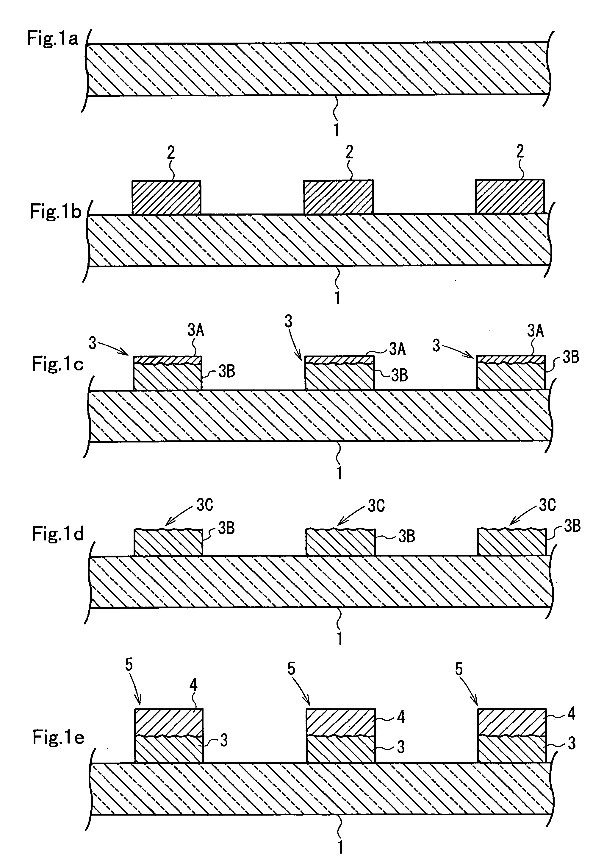
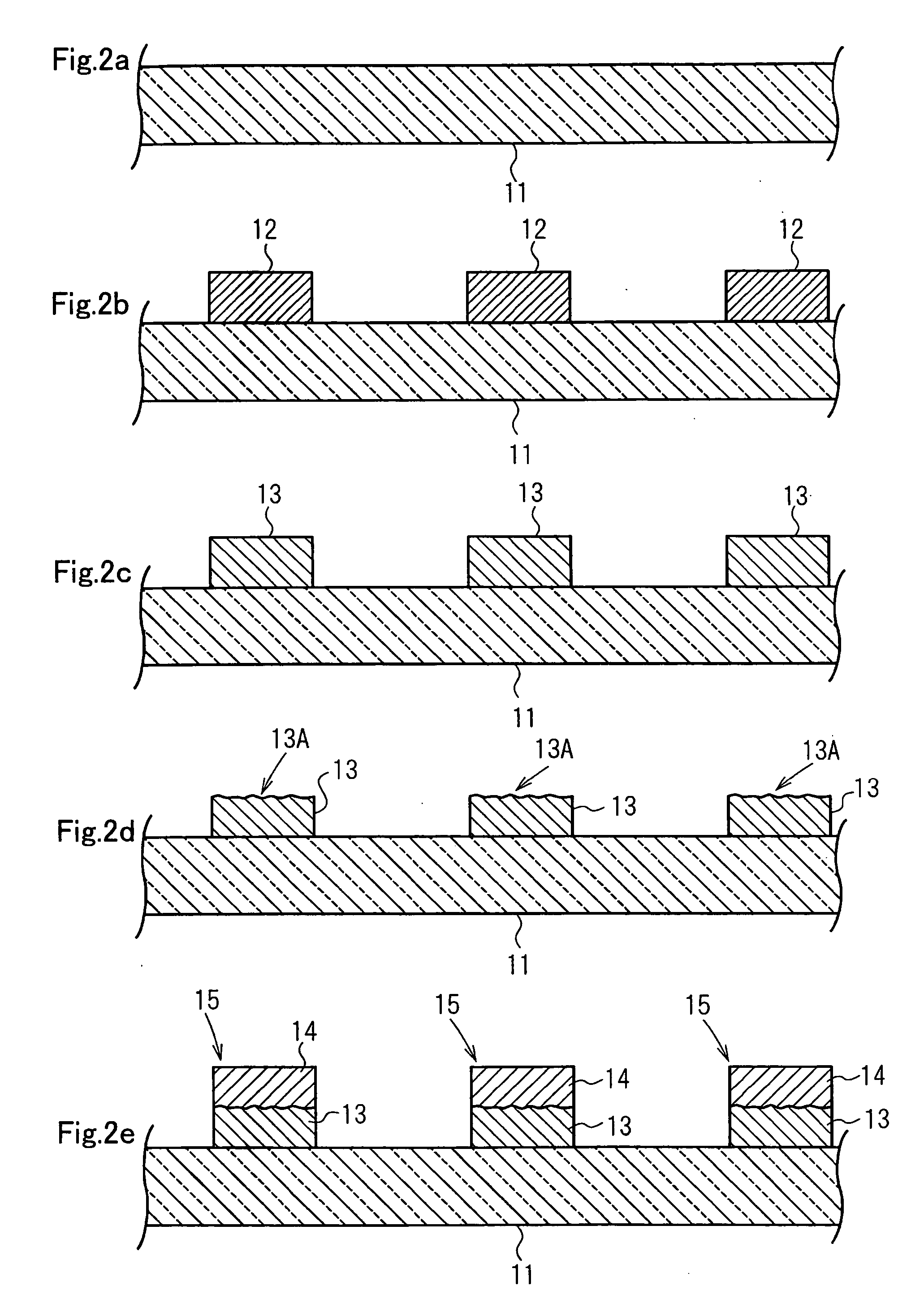
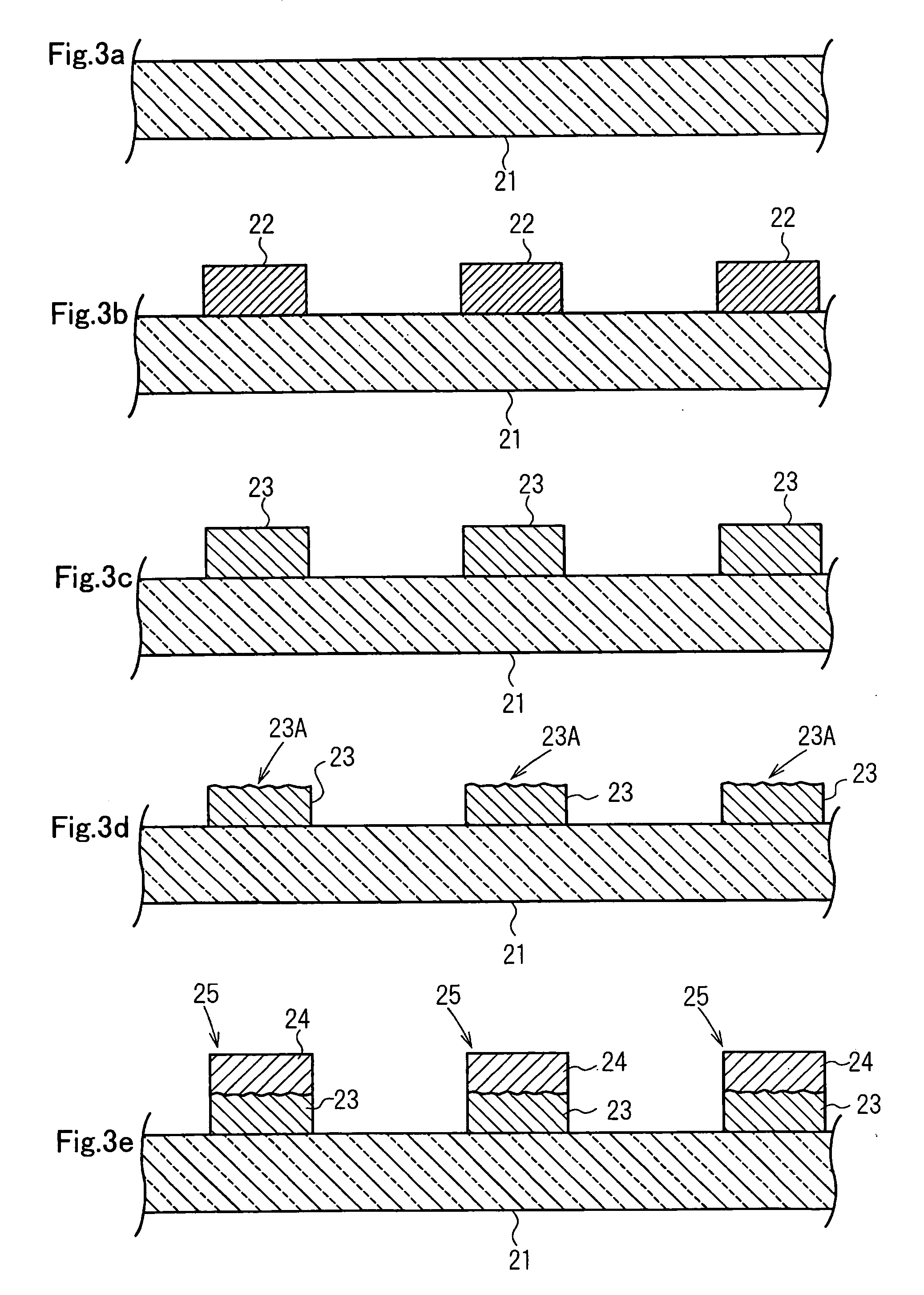
An ultraviolet-curable resin paste containing an electroless plating catalyst is applied by printing to a surface of a transparent substrate 1, and the resulting printed pattern 2 is cured by irradiation of ultraviolet light to form a resin pattern 3. Subsequently, a plating layer 4 is deposited on the resin pattern 3 by electroless plating treatment to form a conductive pattern 5. The resin pattern 3 to be subjected to the electroless plating treatment has an uncured layer 3A provided on a surface thereof. During the electroless plating treatment, the uncured layer 3A is eroded in the plating bath and particles of the catalyst are exposed. It is possible to form a satisfactory plating layer 4 using the exposed catalyst particles as nuclei. By using the ultraviolet-curable resin paste, a good conductive pattern having excellent adhesion to the transparent substrate can be formed with high accuracy, efficiently, and at low cost.
Description
CROSS REFERENCE TO RELATED APPLICATION [0001] This is a continuation application of PCT / JP2004 / 016745 filed on Nov. 11, 2004.FIELD OF THE INVENTION [0002] The present invention relates to electromagnetic-wave-shielding light-transmitting window members useful, for example, as front filters for plasma display panels (PDPs) and window materials (e.g., patch films) for buildings requiring shielding from electromagnetic waves, such as hospitals, and also relates to methods for producing the same. In particular, the present invention relates to an electromagnetic-wave-shielding light-transmitting window member including a transparent substrate and a conductive pattern formed thereon by electroless plating, and a method for producing the same. BACKGROUND OF THE INVENTION [0003] In recent years, along with widespread use of OA equipment, communications equipment, and the like, problems associated with electromagnetic waves generated from such equipment have been receiving attention. There ...
Claims
Login to View More Application Information
Patent Timeline
 IPC IPC(8): B05D5/12B32B15/08B32B27/30G09F9/00H05K9/00
CPCC03C17/34H05K9/0096C03C2217/479C23C18/1608C23C18/1612C23C18/1868C23C18/1879C23C18/1882C23C18/204C23C18/206C23C18/2066C23C18/31H01J2211/446H05K9/0005C03C2217/476
InventorFUNAKI, TATSUYAKOTSUBO, HIDEFUMISASAKI, KIYOMI
OwnerBRIDGESTONE CORP