
Micromachined imaging transducer

Active Publication Date: 2007-02-15
SCI MED LIFE SYST
View PDF15 Cites 120 Cited by
  • Summary
  • Abstract
  • Description
  • Claims
  • Application Information

AI Technical Summary

Benefits of technology

[0006] The present invention generally relates to medical devices, and more particularly to an improved medical imaging device. In one embodiment, an imaging device includes a drive shaft having proximal and distal ends received within the lumen; and an imaging transducer a

Problems solved by technology

However, transducers based on this architecture generally do not operate at frequencies much above 20 Megahertz (“MHz”).

Method used


Image

  • Micromachined imaging transducer
  • Micromachined imaging transducer
  • Micromachined imaging transducer

Examples


Embodiment Construction

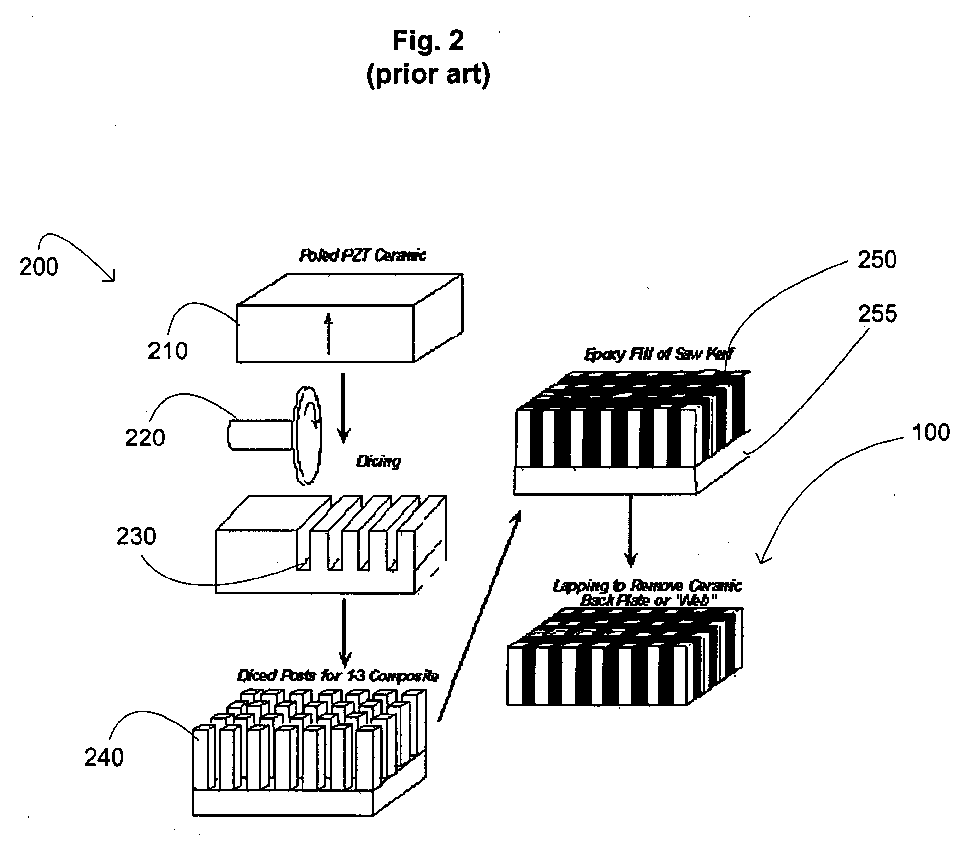
[0018] As mentioned above, an imaging transducer that operates at high frequencies, e.g., frequencies higher than 20 MHz, would be desirable. Such imaging transducers can provide images with higher resolution, which is desirable in applications involving dermatology, ophthalmology, laparoscopy, intracardiac and intravascular ultrasound. One approach to develop such imaging transducers is to utilize a photolithography based micromachining process. An example of such a process 300 is illustrated in FIG. 3.

[0019] In the first step 310, a plate or block of piezoelectric crystal material 315, such as lead magnesium niobate lead titanate (“PMN-PT”) or lead zinc niobate-lead titanate (“PZN-PT”) is obtained. The plate 315 is preferably lapped on both sides and polished on one of the sides. The lapped and unpolished side can then be bonded to a glass carrier (not shown), which is bonded to a silicon, Si, wafer (not shown). The dimensions of the plate 315 are in the range of ten (10) millime...


PUM

PropertyMeasurementUnit
Fractionaaaaaaaaaa
Widthaaaaaaaaaa
Widthaaaaaaaaaa

Abstract

The present invention generally relates to medical devices, and more particularly to an improved medical imaging device. In one embodiment, an imaging device includes a drive shaft having proximal and distal ends received within the lumen; and an imaging transducer assembly coupled to the distal end of the drive shaft and positioned at the distal portion of the elongate member. The imaging transducer assembly includes one or more imaging transducers formed with a piezoelectric composite plate using photolithography based micromachining.

Description

FIELD OF THE INVENTION [0001] The field of the invention relates to imaging devices, and more particularly to micromachined imaging transducers. BACKGROUND OF THE INVENTION [0002] Intraluminal, intracavity, intravascular, and intracardiac treatments and diagnosis of medical conditions utilizing minimally invasive procedures are effective tools in many areas of medical practice. These procedures are typically performed using imaging and treatment catheters that are inserted percutaneously into the body and into an accessible vessel of the vascular system at a site remote from the vessel or organ to be diagnosed and / or treated, such as the femoral artery. The catheter is then advanced through the vessels of the vascular system to the region of the body to be treated. The catheter may be equipped with an imaging device, typically an ultrasound imaging device, which is used to locate and diagnose a diseased portion of the body, such as a stenosed region of an artery. For example, U.S. P...

Claims


Application Information

Patent Timeline
IPC IPC(8): A61B8/14H01L41/22H01L41/23H01L41/332H01L41/337H01L41/39
CPCA61B8/06A61B8/12Y10T29/42A61B8/445B06B1/0629A61B8/14H10N30/853
Inventor REHRIG, PAUL W.JIANG, XIAONINGHACKENBERGER, WESLEY S.YUAN, JIAN R.ROMLEY, RICHARD
Owner SCI MED LIFE SYST
Features
  • Generate Ideas
  • Intellectual Property
  • Life Sciences
  • Materials
  • Tech Scout
  • Unparalleled Data Quality
  • Higher Quality Content
  • 60% Fewer Hallucinations
Learn More