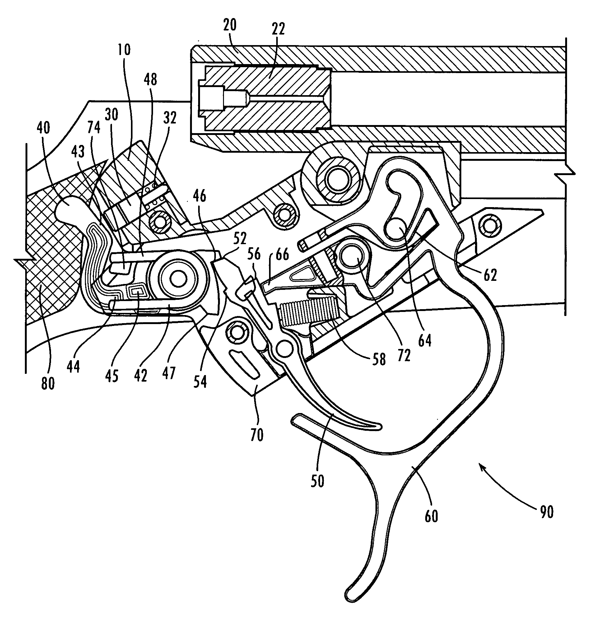
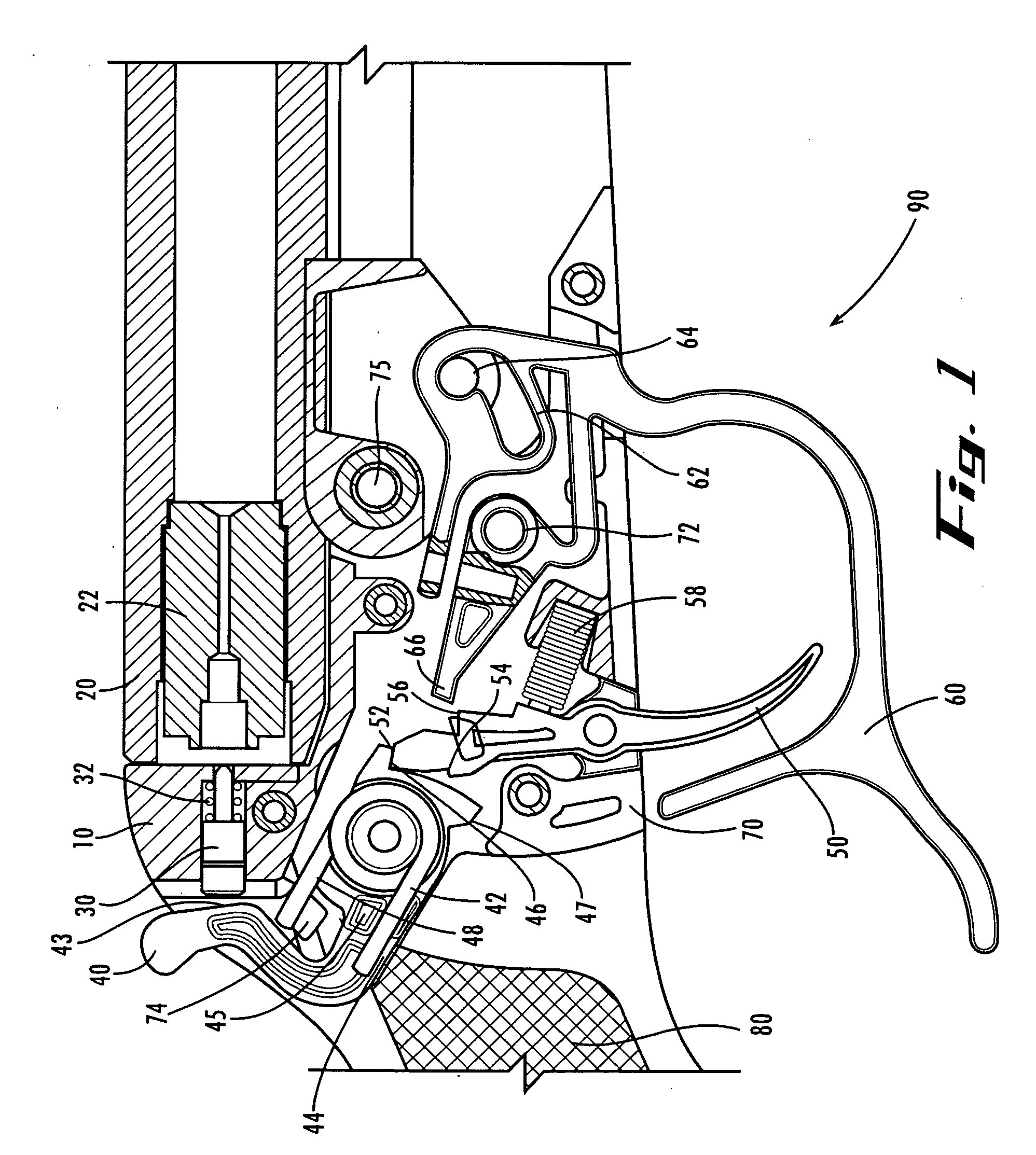
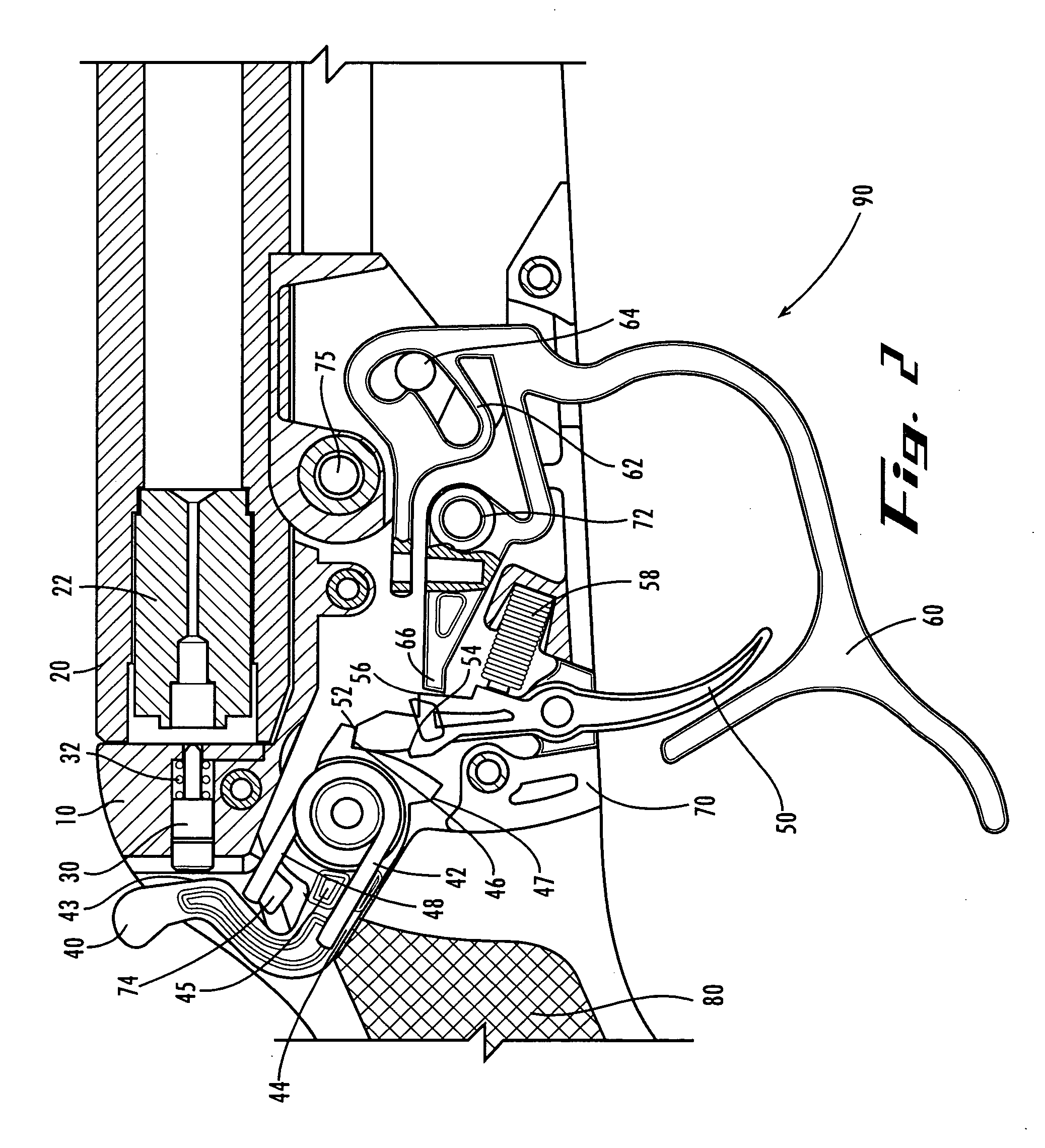
Muzzle-loading firearm with pivoting block action

a firing mechanism and muzzle-loading technology, which is applied in the field of pivoting block firing mechanism of muzzle-loading firearms, can solve the problems of affecting the use of muzzle-loading firearms. the effect of disassembly and cleaning

Inactive Publication Date: 2007-02-22
BLACKPOWDER PRODS
View PDF33 Cites 8 Cited by
  • Summary
  • Abstract
  • Description
  • Claims
  • Application Information

AI Technical Summary

Benefits of technology

[0014] The present invention is an improved muzzle-loading firearm and includes a pivoting firing mechanism set that is pivotally attached to the barrel to allow it to swing down and provide free access to the breech plug in such a way that the percussion cap or primer can be replaced easily. The pivotal range of motion of the pivoting firing mechanism (a pivot block or falling block) allows easy access to the percussion cap in order to replace it, as well as to the breech plug, so it can be disassembled and cleaned out. As used herein, the terms “percussion cap” or “primer” include standard percussion caps as well as 209 shotgun primers and other ignition sources for muzzle-loading firearms.
[0015] Generally described, the present invention is an improved muzzle-loading firearm that has a pivotally attached firing mechanism (pivot block) and includes a mechanism for providing a positive prevention of unwanted movement from a blocked position to an unblocked position. The invention preferably also prevents inadvertent tripping of the firing mechanism when the pivot block is swung down to its unblocked position.
[0017] Preferably, the trigger guard is held in its locked, blocked position by a spring clamp. An advantage of the spring clamp arrangement is that it tends to hold the trigger guard in its locked, blocked position, but does not apply a biasing force biasing the trigger guard against movement from the unlocked, blocked position toward the unlocked, unblocked position, thereby making it relatively easy to move the pivot block to its unblocked position. Alternatively, the trigger guard can be biased toward its locked, blocked position by a biasing spring.

Problems solved by technology

Meanwhile, developments in the older, outdated muzzle-loading firearms slowed as the muzzle-loading firearms fell out of favor.
Despite their recent increased popularity, muzzle-loading firearms have presented several problems to those that use them.
However, whether they are traditional or in-line, these firearms typically have problems in common.
Such deficiencies of the firearms include the following: Excessive Residue: The black powder that is used in shooting these firearms typically leaves residue on both the barrel and the firing mechanisms.
This disassembly is difficult and time-consuming, and obtaining an acceptable cleaning result without disassembling all, or a substantial part, of the firearm is very difficult.
Additionally, the traditional type of muzzle-loading firearms are even more difficult to clean, making the residue problem even more severe.
Blowback Gas Injuries: Shooting muzzle-loading firearms often causes “blowback gas.” This gas, which is a byproduct of the burning of the black powder, can cause injury and burns to the shooter.
However, traditional models face a problem when a left-handed shooter uses a firearm intended to be for a right-handed person.
This problem is typically worse for in-line models, as access for reloading the percussion caps or other form of primers is very difficult and a user typically must use a special tool for this purpose.
Barrel Length: Because of the type of powder used, these types of firearms typically have relatively long barrels, making them rather heavy.
As previously discussed, previously known in-line rifles have problems with regard to the blowback gas and with the long reloading times. Additionally, this type of rifle also has another disadvantage in comparison to traditional muzzle-loading rifles, as they often have a longer overall length for a given effective barrel length (i.e., the length of the bore into which the powder charge and bullet are loaded), because the firing mechanism and primer loading action are located behind the barrel (rather than beside it), and similarly may also have a greater weight for a given effective barrel length than traditional side-action rifles.

Method used


Image

  • Muzzle-loading firearm with pivoting block action
  • Muzzle-loading firearm with pivoting block action
  • Muzzle-loading firearm with pivoting block action

Examples


Embodiment Construction

[0035] The present invention may be understood more readily by reference to the following detailed description of the invention taken in connection with the accompanying drawing figures, which form a part of this disclosure. It is to be understood that this invention is not limited to the specific devices, methods, conditions or parameters described and / or shown herein, and that the terminology used herein is for the purpose of describing particular embodiments by way of example only and is not intended to be limiting of the claimed invention. Also, as used in the specification including the appended claims, the singular forms “a,”“an,” and “the” include the plural, and reference to a particular numerical value includes at least that particular value, unless the context clearly dictates otherwise. Ranges may be expressed herein as from “about” or “approximately” one particular value and / or to “about” or “approximately” another particular value. When such a range is expressed, anothe...


PUM


Abstract

A muzzle-loading firearm having a barrel and a pivoting firing mechanism. The barrel has a breech plug, a pivoting junction axle, and a blocking axle, and the firing mechanism has a trigger, hammer, striker and notch. The firing mechanism is pivotally attached to the barrel at the pivoting junction axle and the blocking axle is movably aligned in the notch. When the firing mechanism is pivoted, it is guided by the blocking axle in the notch ensuring sufficient clearance between said firing mechanism for easy placement of a percussion cap.

Description

CROSS-REFERENCE TO RELATED APPLICATIONS [0001] The present application claims the priority benefit of U.S. Provisional Patent Application Ser. No. 60 / 425,950, filed Nov. 12, 2002; U.S. Provisional Patent Application Ser. No. 60 / 443,936 filed Jan. 31, 2003; and U.S. Provisional Patent Application Ser. No. 60 / 497,420, filed Aug. 22, 2003; all of which are hereby incorporated herein by reference in their entireties.TECHNICAL FIELD [0002] The present invention relates to a firing mechanism for a muzzle-loading firearm, such as a muzzle-loading rifle, shotgun, cannon or the like. This invention relates more specifically toward a pivoting block firing mechanism for a muzzle-loader. BACKGROUND OF THE INVENTION [0003] In the second half of the 19th century, cartridge style rifles became popular and the market for older muzzle-loading designs started to wane. After the introduction of the cartridge style rifle, which fires a pre-assembled cartridge or bullet, firearm manufacturers started de...

Claims


Application Information

Patent Timeline
Patent Type & Authority Applications(United States)
IPC IPC(8): F41C7/00F41A3/06F41C9/08F42C7/06
CPCF41A3/06F42C7/06F41C9/08F41C7/06
Inventor LIZARRALDE, INIGOECHEBERRIA, JULIAN
Owner BLACKPOWDER PRODS
Why Eureka
Try Eureka