Module for heating the intake gases of an internal combustion engine incorporating electronic temperature control

a technology of electronic temperature control and intake gas, which is applied in the direction of engine components, mechanical equipment, fuel treatment, etc., can solve the problems of increased heat loss, difficult to ensure, and none of the functions enabling the heating module to be fitted in the plastic intake manifold

Inactive Publication Date: 2007-02-22
NAGARES
View PDF12 Cites 22 Cited by
  • Summary
  • Abstract
  • Description
  • Claims
  • Application Information

AI Technical Summary

Benefits of technology

[0002] The object of the invention is to enable the heating module to be installed in an intake manifold, preferably of plastic, without damaging the same due to excess temperature, and optimising the performance of the engine, which is achieved through measurement of one of the representative temperatures of the heating module and the insertion of the control electronics between the supply source and the heating element so that the accidental or intentional connection of said heating element to the battery is prevented.

Problems solved by technology

However, none of these functions enables the heating module to be fitted in the plastic intake manifold, optimising engine performance and ensuring that damage to the said manifold will be caused by excess temperature under any circumstance.
As we shall see, the more efficiently these design conditions are met, the better the operating temperature of the resistance, and hence the greater will be the losses of heat through the frame of said resistance to its surrounding area and the more difficult it will be ensure that damage to the manifold will not be caused by excess temperature in the event of “degraded” operation.
us the following: 1) minimum charge loss 2) high dissipated power 3) short response times 4) relatively high operating temperature, which imposes a disadvantage (impossibility) in terms of fitting the heating module in the plastic manifold.
This means that the heating modules designed on the basis of these guidelines, which are those deriving from the aforementioned patents, could be installed in plastic manifolds, but to the detriment of the engine performance characteristics, such as: 1) Loss of power (charge losses at the intake result in a slower air flow to the inlet of the cylinders and loss power).
2) Longer starting times (longer pre-ignition time) 3) Higher pollution emissions due to the long response times prevent sophisticated heating strategies for the intake gases following sudden accelerations and decelerations of the engine.

Method used


Image

  • Module for heating the intake gases of an internal combustion engine incorporating electronic temperature control
  • Module for heating the intake gases of an internal combustion engine incorporating electronic temperature control
  • Module for heating the intake gases of an internal combustion engine incorporating electronic temperature control

Examples


Embodiment Construction

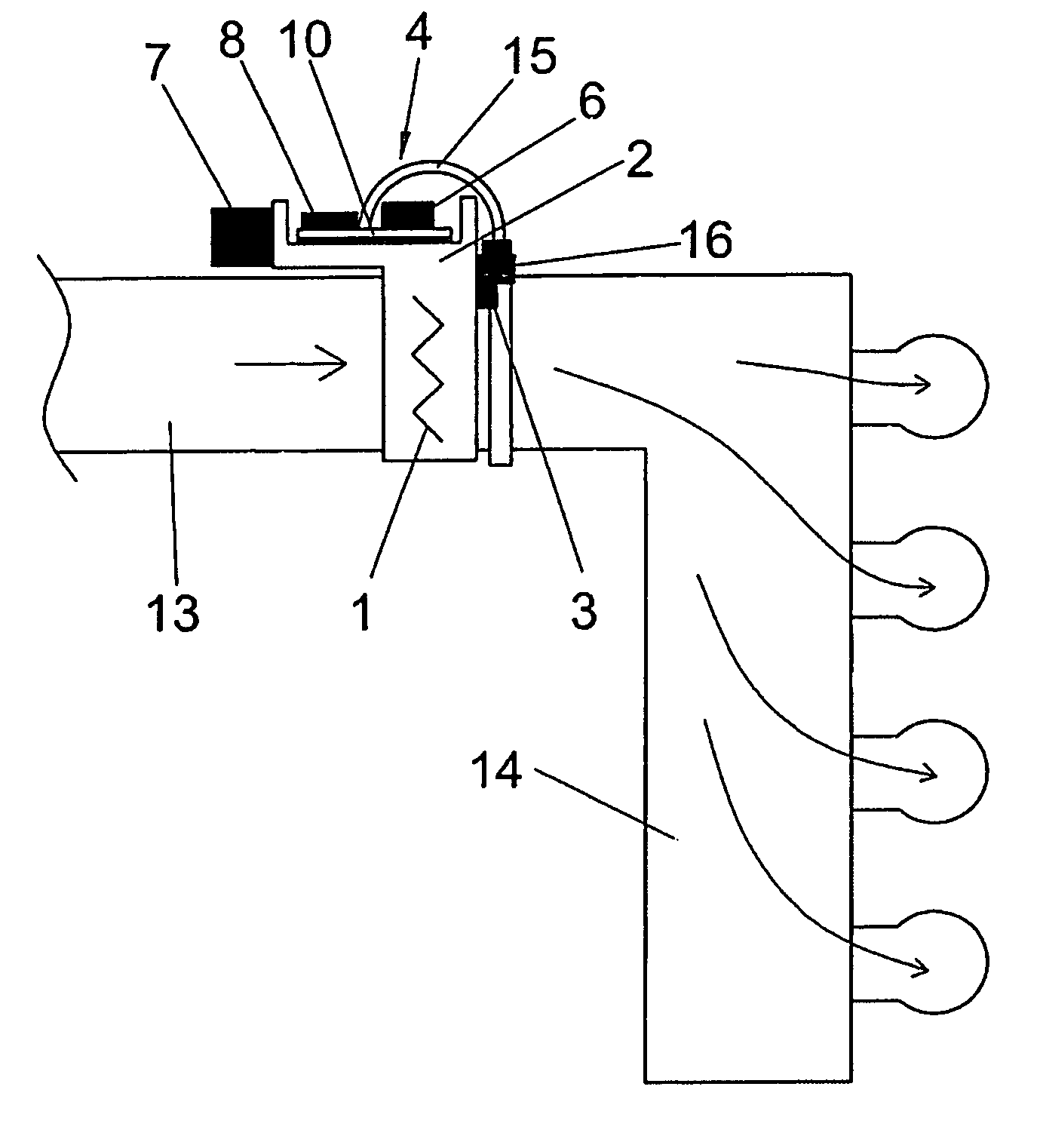
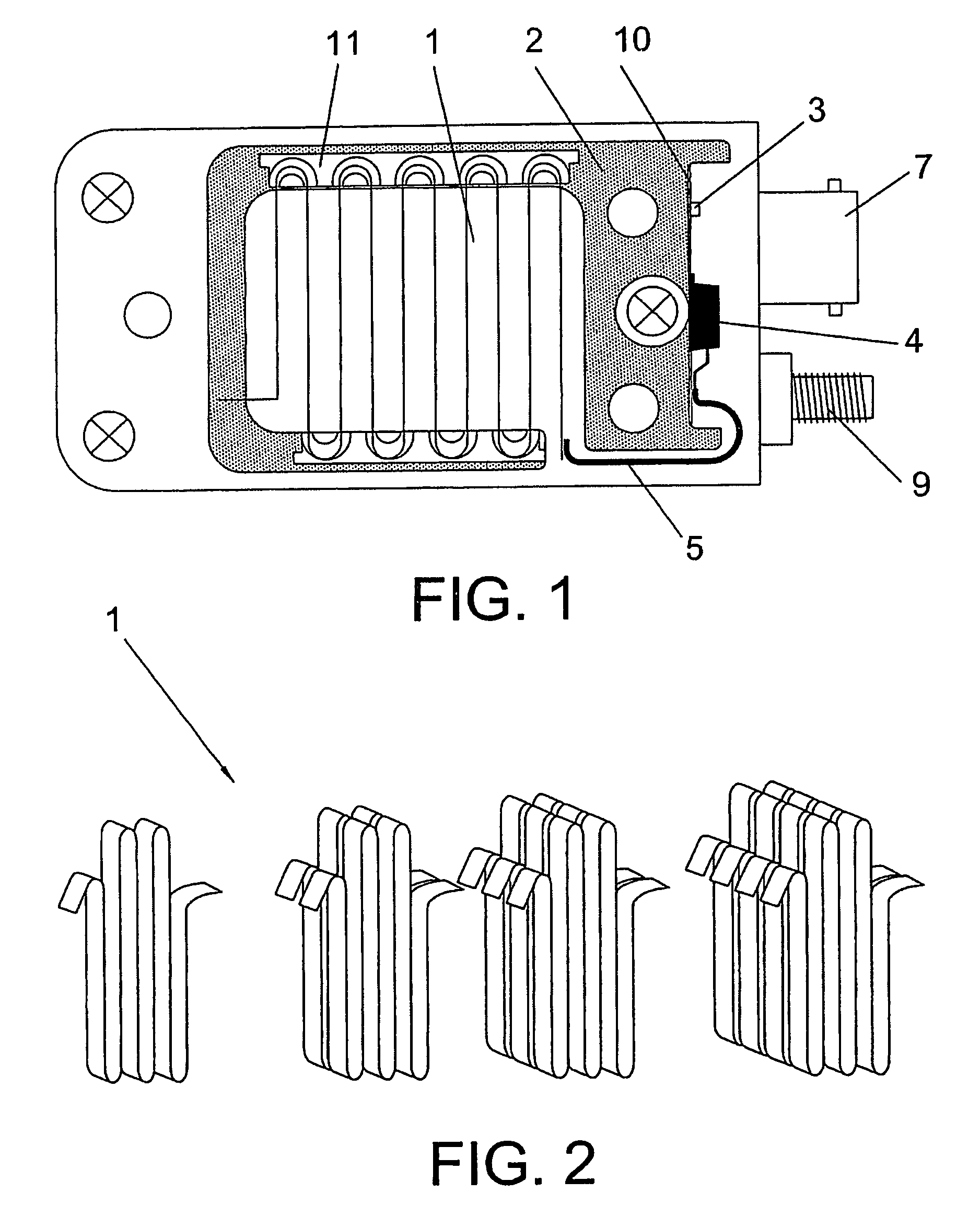
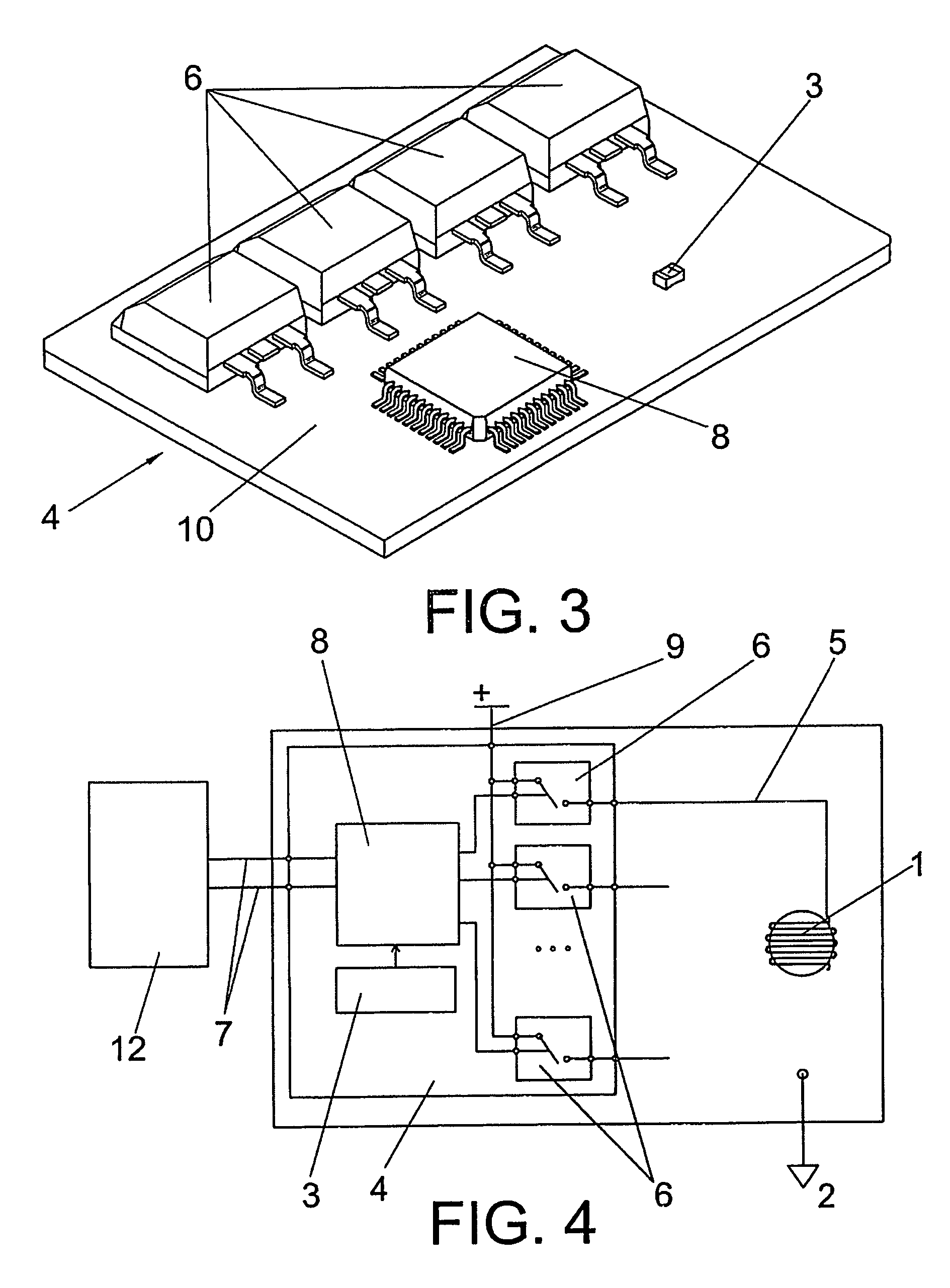
[0035] The module for heating the intake gases of an internal combustion engine, incorporating electronic temperature, according to this invention, satisfactorily solves the problem outlined in each of the points previously described, comprising two fundamental parts: a heating element (resistance in the form of a continuous strip), and a power control circuit which measures a representative temperature of the heating module and manages the distribution of electricity in the heating element, which parts are located or integrated in the same frame of metal, preferably aluminium.

[0036] Within the same heating module the heating element is installed so that it is insulated from the frame by means of ceramic insulants on which it rests and expands freely to absorb their expansions, thereby preventing them from deforming. This heating element is connected electrically at one of its ends to the frame, by means of which it is earthed, and it is connected at the other end by means of a con...


PUM


Abstract

Used for heating the gases circulating through an intake manifold (13), preferably of a plastic material, by means of heating element (1), incorporating a metal frame (2) in which is adhered the power control circuit (4), and in which is installed the heating element (1), both forming the same module to provide electronic control of the temperature of the intake gases in the intake manifold, preventing the maximum temperature of the plastic of the intake manifold from being exceeded. The power control circuit (4) incorporates essentially a control logic (8), which is connected a temperature sensor (3) and at least one power switch (6), which controls the heating element (1), the temperature sensor (3) being preferably integrated in the power control circuit (4).

Description

OBJECT OF THE INVENTION [0001] This invention relates to a heating module used for heating the gases which are introduced through the intake pipe of an internal combustion engine incorporating electronic temperature control, consisting of the following fundamental parts: heating element (resistance in the form of a continuous strip), and power control circuit which measures a temperature representative of the heating module and which manages the distribution of electrical energy in the heating element. [0002] The object of the invention is to enable the heating module to be installed in an intake manifold, preferably of plastic, without damaging the same due to excess temperature, and optimising the performance of the engine, which is achieved through measurement of one of the representative temperatures of the heating module and the insertion of the control electronics between the supply source and the heating element so that the accidental or intentional connection of said heating...

Claims


Application Information

Patent Timeline
Patent Type & Authority Applications(United States)
IPC IPC(8): F02M31/13
CPCF02M31/13F02M35/10019F02M35/10249Y02T10/126F02M35/1038F02M35/112F02M35/10268Y02T10/12
Inventor NAVALON CARRETERO, HERMINIO
Owner NAGARES
Why Eureka
Try Eureka