Seal assembly for ultrahigh-pressure vessels

a technology of ultra-high pressure and seal assembly, which is applied in the direction of engine seals, container filling methods, container discharging methods, etc., can solve the problems of difficult sealing of fluids at extremely high pressures, pressures in excess of 15,000 psi, and greater pressures, e.g., up to and beyond 75,000 psi, so as to improve the integrity of the seal assembly and improve the quality and longevity of the seal

Inactive Publication Date: 2007-02-22
AVURE TECH
View PDF14 Cites 8 Cited by
  • Summary
  • Abstract
  • Description
  • Claims
  • Application Information

AI Technical Summary

Benefits of technology

[0007] The present invention is directed towards seals and seal systems for use with high-pressure fluid containment systems, such as ultrahigh-pressure cylinders. Embodiments of the invention allow a plug or other closure to be selectively engaged and disengaged from a pressure vessel, while effecting a fluid seal at high pressures. Embodiments of the invention improve the integrity of the seal assembly as compared to prior art sealing systems, thereby improving the quality and longevity of the seal.

Problems solved by technology

Sealing fluids at extremely high pressures, i.e., pressures in excess of 15,000 psi, and even greater pressures, e.g., up to and beyond 75,000 psi, can be extremely difficult.
However, high-pressure systems, for example high-pressure vessels, are difficult to seal because the tremendous pressures acting on a polymer seal tend to extrude the seal.
Furthermore, high-pressure vessels that are large in diameter are even more difficult to seal, given that pressurization causes the expansion of the vessel, thereby widening any existing gap through which the seal may attempt to extrude.
During pressure cycles, movement of the metal ring and seal, combined with interface frictional forces, cause wear and degradation of both the support ring and polymer seals, leading to the failure of the seal assembly.
The expansion and movement of the vessel components and seal assembly resulting in relative movement between the metallic support ring and the vessel wall, also causes galling and or scratching of the vessel wall, which ultimately results in seal failure.
Previous attempts have been made to solve this problem by applying a hard coating to the metal support ring, however, such attempts have been unsuccessful.

Method used


Image

  • Seal assembly for ultrahigh-pressure vessels
  • Seal assembly for ultrahigh-pressure vessels

Examples


Embodiment Construction

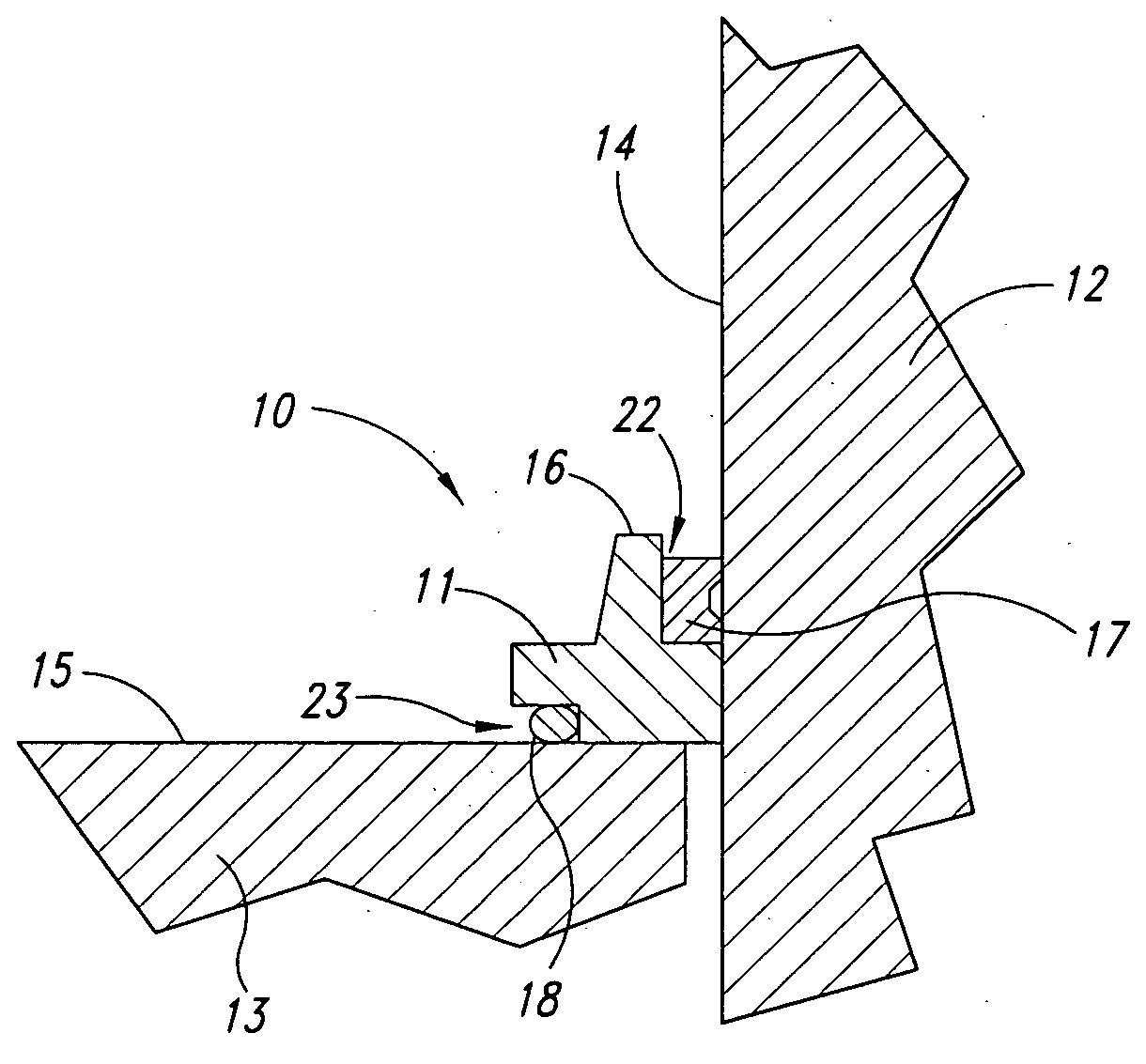
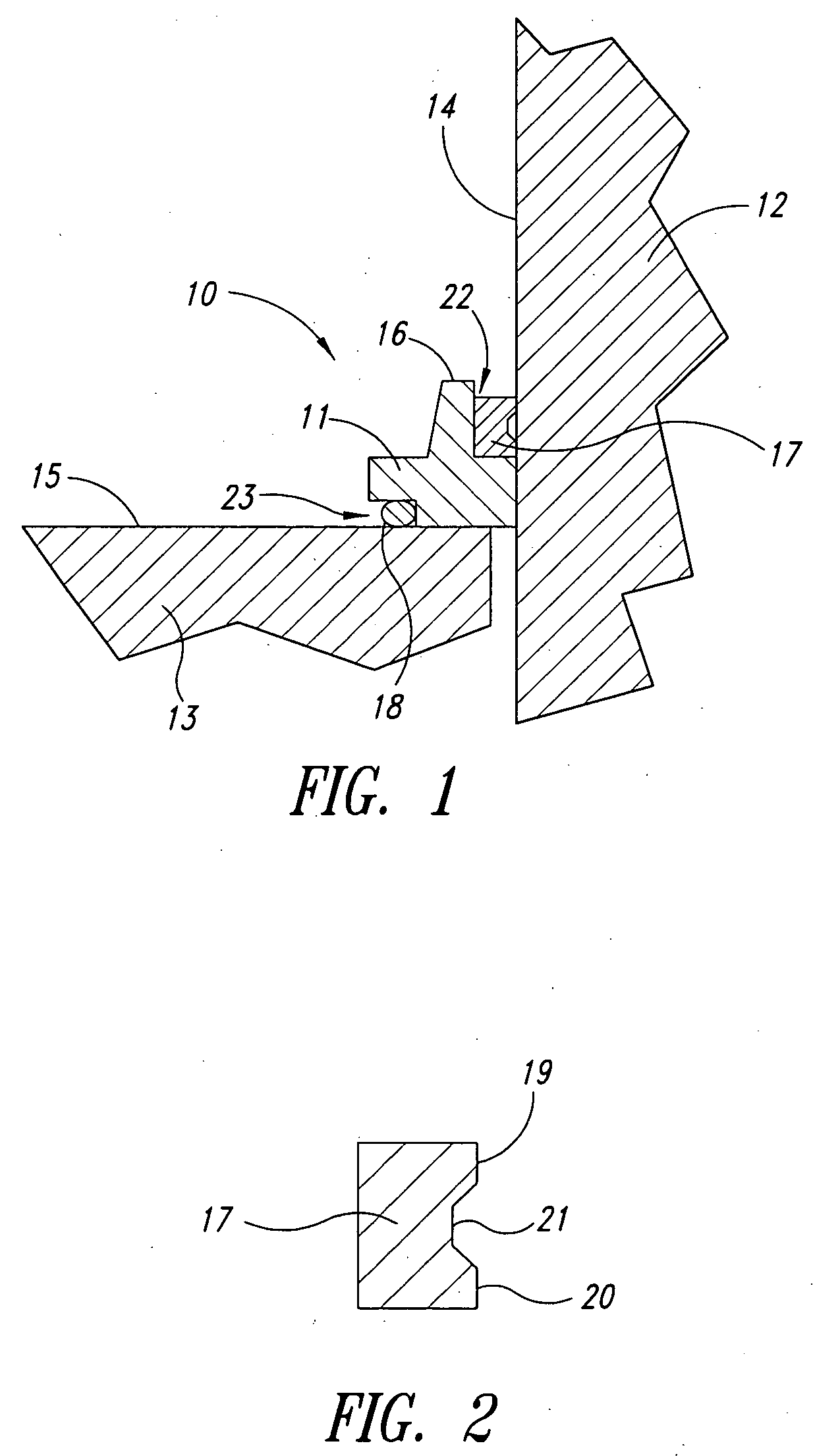
[0012] The present invention is directed toward seals in sealing systems for high pressure fluid containment, such as high pressure vessels. In one embodiment, as illustrated in FIG. 1, a seal assembly 10 comprising a metal support ring 11, a first polymer seal 17 and a second polymer seal 18 is positioned adjacent a first sealing surface 14, such as a wall of a pressure vessel 12, and a second sealing surface 15, for example an inner surface of an enclosure 13.

[0013] As discussed previously, the vessel 12 and closure 13 expand and move relative to each other as the pressure in the vessel cycles up and down. The radial and axial expansion and movement of the vessel wall 12, closure 13 and seal assembly 10, results in relative movement between the support ring 11 and vessel wall 12. In conventional systems, this results in galling and scratching of the vessel wall 12 which in turn causes damage to the polymer seal, resulting in seal failure.

[0014] These problems are substantially a...


PUM


Abstract

A seal assembly is provided to seal a pressure vessel and an adjacent enclosure. A metal support ring configured to contact a first sealing surface and a second sealing surface when installed in a pressure vessel, is provided with a low friction coating with transferable low friction additives which results in the transfer of a solid lubricant film onto the vessel wall enclosure. Two polymer seals are provided adjacent the metal support ring and the pressure vessel and enclosure respectively, the polymer seals having a configuration and being formed of a high resilience material, to increase the longevity of the seal assembly.

Description

BACKGROUND OF THE INVENTION [0001] 1. Field of the Invention [0002] The present invention relates to fluid seals, and more particularly, to devices and systems for sealing fluids at very high pressures. [0003] 2. Description of the Related Art [0004] Sealing fluids at extremely high pressures, i.e., pressures in excess of 15,000 psi, and even greater pressures, e.g., up to and beyond 75,000 psi, can be extremely difficult. While at low pressures of a few hundred psi, many polymers have the strength to bridge gaps up to many millimeters. However, high-pressure systems, for example high-pressure vessels, are difficult to seal because the tremendous pressures acting on a polymer seal tend to extrude the seal. Thus, it is necessary in high-pressure environments to have tight clearances between any support for a polymer seal and the sealing surface. Furthermore, high-pressure vessels that are large in diameter are even more difficult to seal, given that pressurization causes the expansio...

Claims


Application Information

Patent Timeline
Patent Type & Authority Applications(United States)
IPC IPC(8): F17C13/06
CPCF16J15/127
Inventor TING, EDMUND Y.ENGSTROM, NICLASMONSERUD, DAVID O.
Owner AVURE TECH
Why Eureka
Try Eureka