

Method and apparatus for digital demodulation and further processing of signals obtained in the measurement of electrical bioimpedance or bioadmittance in an object
- Summary
- Abstract
- Description
- Claims
- Application Information
AI Technical Summary
Benefits of technology
Problems solved by technology
Method used
Image

Examples
first embodiment
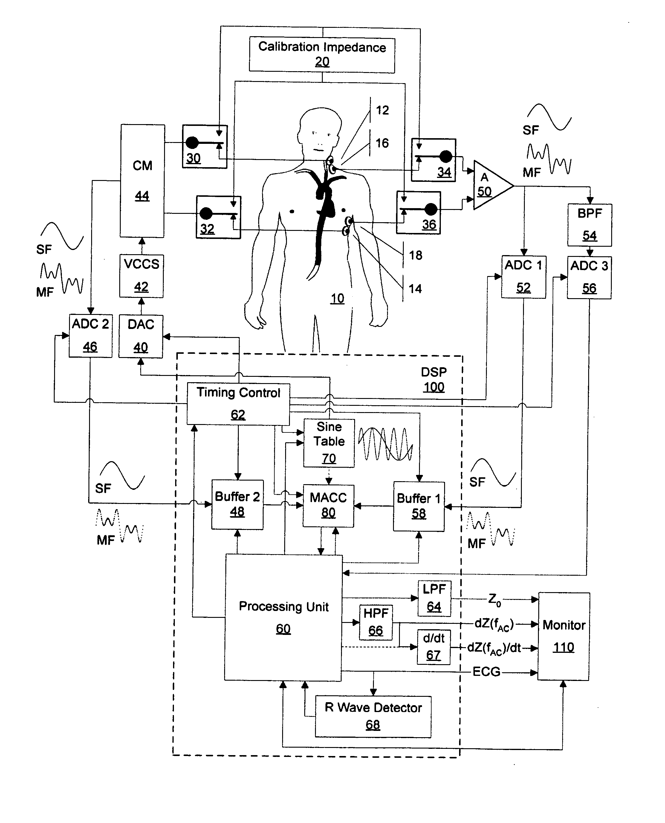
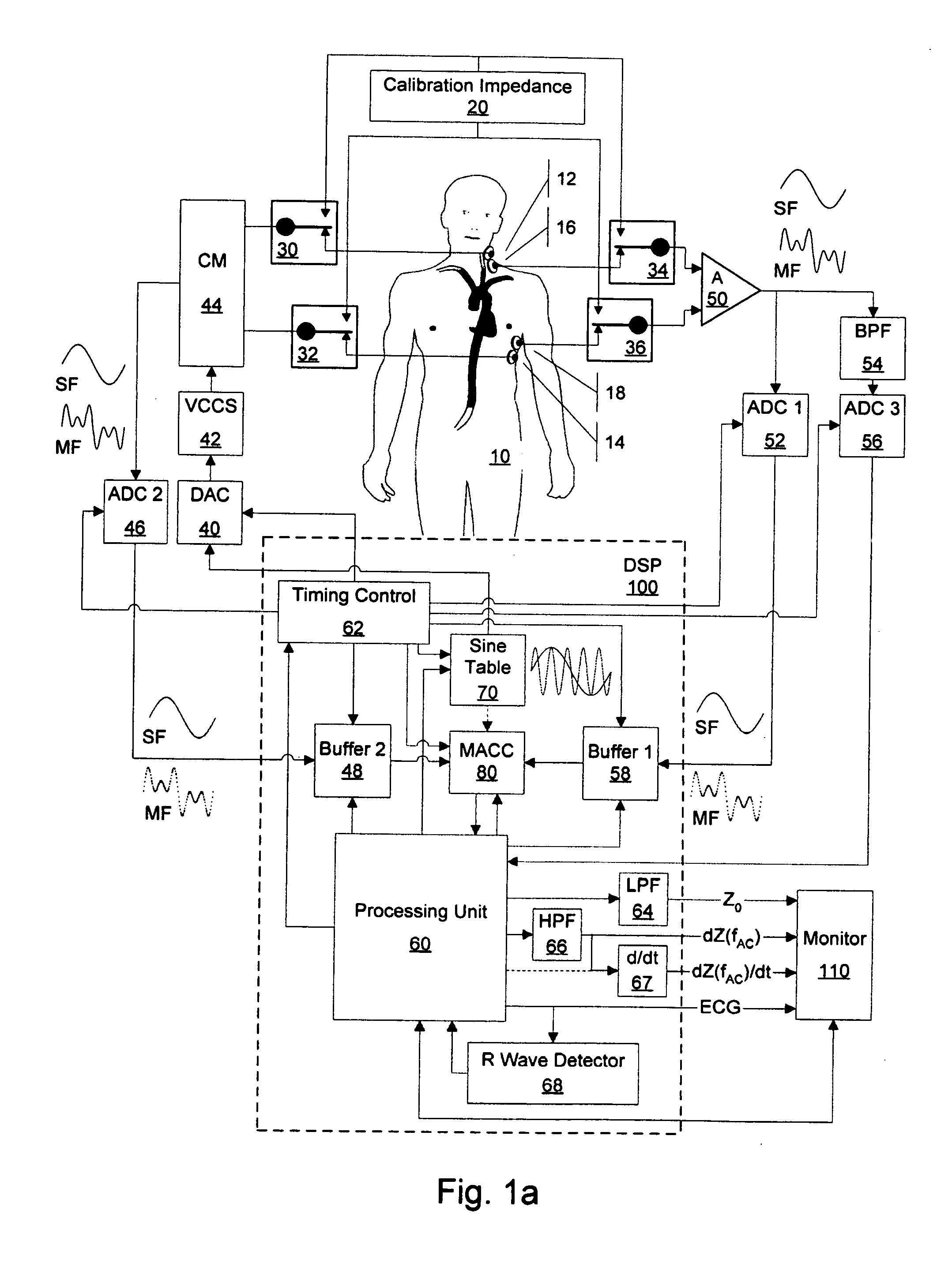
[0135] FIG. 4a and 4b, the voltage controlled current source (VCCS) 42, which generates a single frequency (SF) or multi-frequency (MF) alternating current (AC), and the differential amplifier (A) 50 are switched to the calibration impedance 20, and the alternating current (AC) applied and the resulting voltage are measured, amplified and digitized.
[0136] In the event of a single frequency (SF) alternating current (AC) application, because the frequency of the measured alternating current (AC) applied and, thus, of the voltage measured is known, the samples measured, amplified and digitized can be fitted towards discrete values of an ideal sinusoidal waveform using commonly known fitting processes.
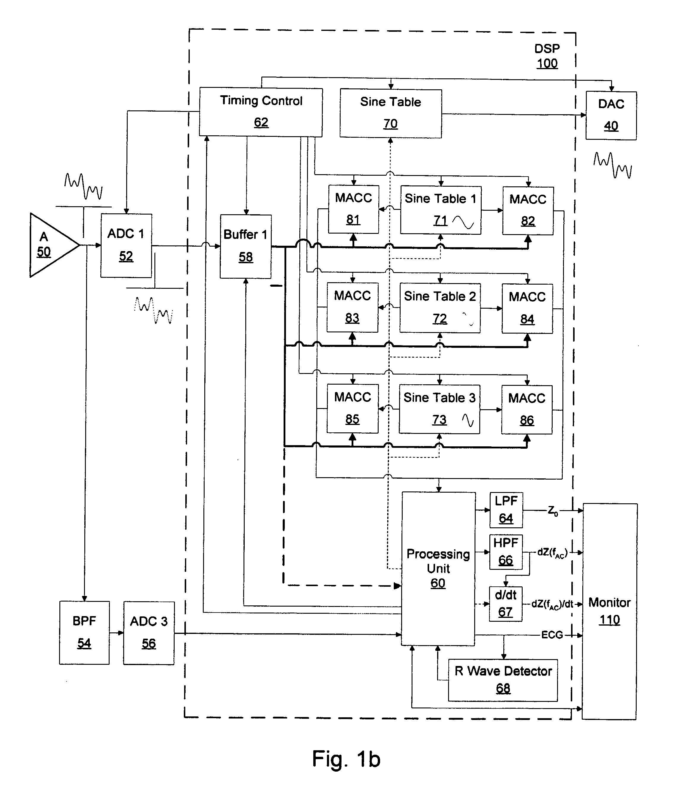
[0137] Then, in a process further referred to as indirect correlation, for each frequency fAC of the alternating current (AC) applied, the amplified, digitized and optionally fitted samples obtained from the measurement of the alternating current (AC) applied are correlated with the disc...
second embodiment
[0141] FIG. 5, the voltage controlled current source (VCCS) 42, which generates a single-frequency (SF) alternating current (AC), and the differential amplifier (A) 50 are switched to the calibration impedance 20, and the alternating current (AC) applied and the resulting voltage are measured, amplified and digitized.
[0142] Because the frequency of the alternating current (AC) applied and, thus, of the voltage measured is known, the samples obtained, amplified and digitized can be fitted towards discrete values of an ideal sinusoidal waveform using commonly known fitting processes.
[0143] Then, in a process further referred to as direct correlation, the amplified, digitized and optionally fitted samples obtained from the measurement of the voltage and obtained from the measurement of the alternating current (AC) applied are correlated.
[0144] Thereafter, the aforementioned processes are performed with the current source (VCCS) 42 and to the differential amplifier 50 switched to the...
third embodiment
[0146] FIG. 6, the voltage controlled current source (VCCS) 42, which generates a single frequency (SF) or multi-frequency (MF) alternating current (AC), and the differential amplifier (A) 50 are switched to the calibration impedance 20 but only the resulting voltage is measured, amplified and digitized.
[0147] In the event of a single frequency (SF) alternating current (AC) application, because the frequency of the alternating current (AC) applied and, thus, the frequency of the measured voltage is known, the samples obtained, amplified and digitized can be fitted towards discrete values of an ideal sinusoidal waveform using commonly known fitting processes.
[0148] Then, for each frequency fAC of the alternating current (AC) applied, the amplified, digitized and optionally fitted samples obtained from the voltage measurement are correlated with the discrete values of an ideal sine waveform in order to obtain a value proportional to the in-phase portion IV (fAC) of the voltage and c...
PUM
 Abstract
Description
Claims
Application Information