Flexible Fingerprint Sensor

a fingerprint sensor and flexible technology, applied in the field of pressure sensors, can solve the problems of significantly lower electrical power consumption of the device per fingerprint image capture operation, and achieve the effects of low cost, less manufacturing cost, and adequate resolution

Active Publication Date: 2008-04-24
ANTAKI PATRICK R
View PDF23 Cites 37 Cited by
  • Summary
  • Abstract
  • Description
  • Claims
  • Application Information

AI Technical Summary

Benefits of technology

[0017]The present invention provides a fingerprint sensor that is low cost, thin, mechanically conforming, mechanically flexible and provides adequate resolution such that it can be used on hand-held devices, credit and debit cards, identification badges and cards, and the like. This invention discloses a novel method of manufacturing a fingerprint sensor which is mechanically flexible and costs less to manufacture than currently known methods. The sensor includes a compressible and flexible core material layered in between two orthogonally arranged electrical conductive wires. The core material's electrical resistance varies according to applied pressure. The orthogonal wiring arrangement allows an external electronic circuit to successively scan each geometric intersection of the array in order to measure the local resistance. The variation in electrical resistance across the array corresponds to the applied fingerprint's pattern. This invention does not use any active electronic components such as transistors, and does not require the application of any semiconductor manufacturing techniques. As a result, the device consumes significantly lower electrical power per fingerprint image capture operation than other methods. In addition, all of the manufacturing materials and processes required to manufacture the sensor disclosed in this invention are compatible with large-scale low cost and high volume production. Moreover, the device is capable of sustaining mechanical stresses and long term “abuse” in a fault-tolerant manner. As a result, the present invention enables the manufacture of very low-cost fingerprint sensors for incorporation into many day-to-day consumer items such as cell phones, credit cards, purses, wallets, etc.

Problems solved by technology

As a result, the device consumes significantly lower electrical power per fingerprint image capture operation than other methods.

Method used


Image

  • Flexible Fingerprint Sensor
  • Flexible Fingerprint Sensor
  • Flexible Fingerprint Sensor

Examples


first embodiment

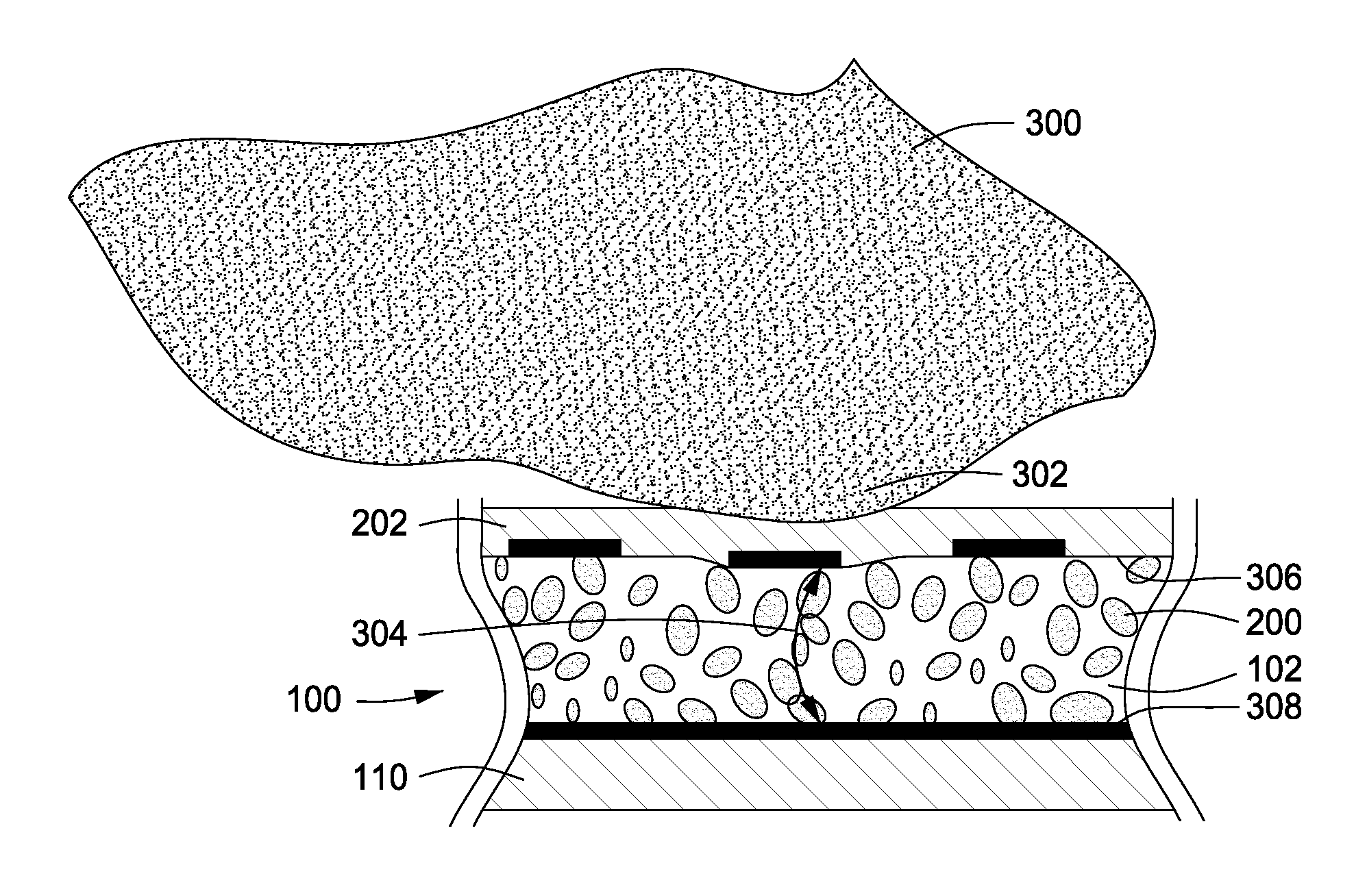
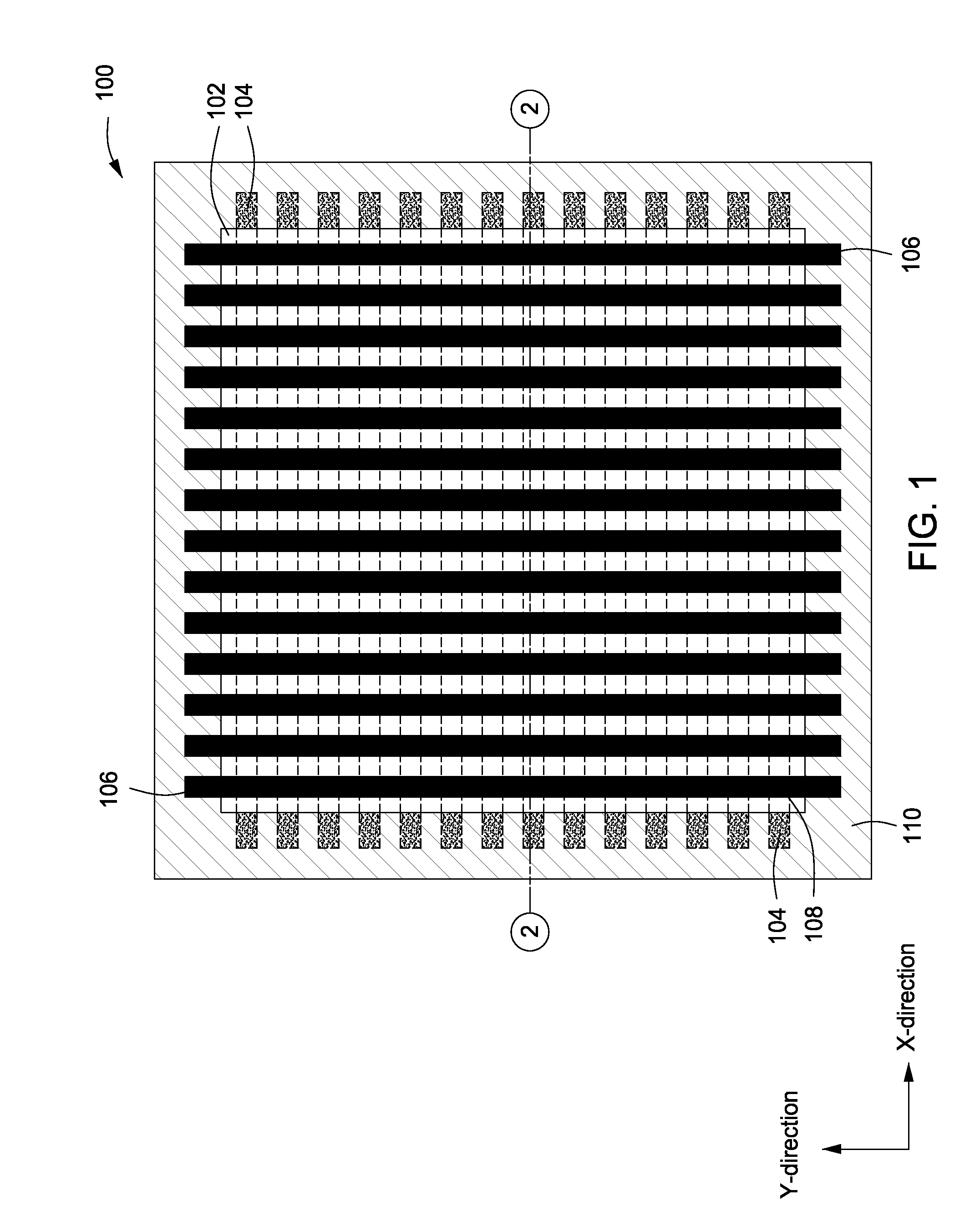
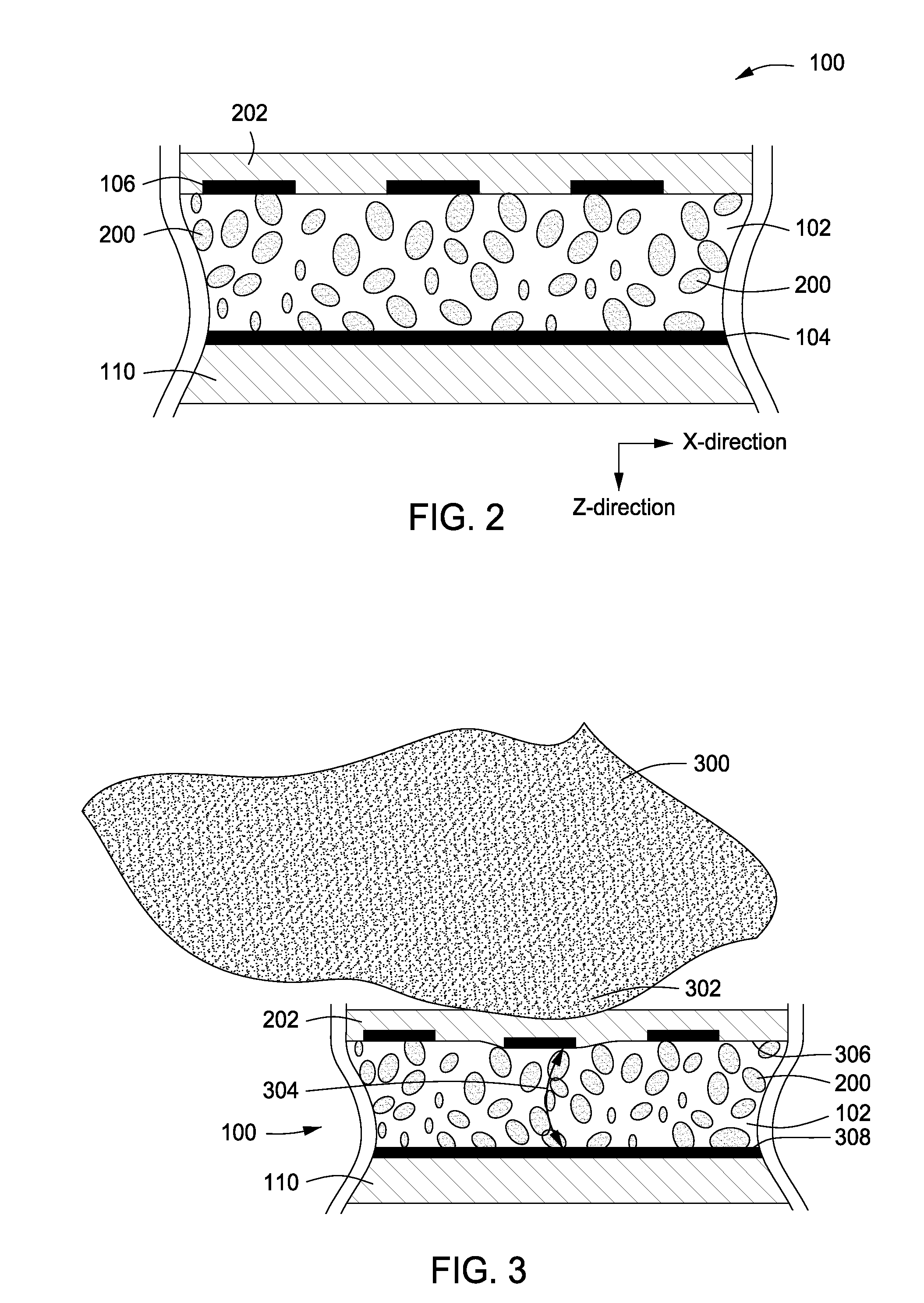
[0042]Now referring to FIG. 1, a top view of a flexible fingerprint sensor 100 in accordance with the present invention is shown. A simplified 14×14 array is shown for discussion purposes; however, a practical implementation would have at least 200-300 lines on each side. The fingerprint sensor 100 includes of a series of layers of materials. At the center is a bulk soft, compressible and elastic material, such as a polymer or an elastomer (hereinafter referred to as the base material or composite material 102). The base material or composite material 102 is impregnated with small electrically conductive particles (not shown). In other words, the conductive particles are at least partially embedded in an elastomeric layer. The conductive particles can be metal, core particles having a conductive coating, carbon nanotubes, carbon nanofibers, conductive fibers, or a combination thereof. The conductive particles are distributed homogeneously with no relative orientation within the comp...

second embodiment

[0049]Referring now to FIGS. 6 and 7, a top view (FIG. 6) and a cross section view (FIG. 7) of a flexible fingerprint sensor 600 in accordance with the present invention are shown. In this embodiment, it is possible to eliminate the top-most layer of conductor carrying material. This is useful in order to further increase the spatial resolution of the sensor by eliminating any special buffering that this top layer exhibits. The column (y-direction) conductors are still required in order for the electrical scanning circuit to be completed. The flexible pressure sensor 600 has a first set of substantially parallel conductors 104 in the x direction and a composite material 102 in contact with the first set of conductors 104. The composite material 102 includes a first set of conductive particles 602 and a second set of conductive particles 200 all of which are at least partially embedded in an elastomeric layer that is capable of returning to substantially its original dimensions on re...

third embodiment

[0052]Referring now to FIG. 10, a cross sectional view of a flexible fingerprint sensor 1000 in accordance with the present invention is shown. The flexible pressure sensor 1000 has a composite material 102 that includes a first set of conductive particles 1002, a second set of conductive particles 602 and a third set of conductive particles 200 all of which are at least partially embedded in an elastomeric layer that is capable of returning to substantially its original dimensions on release of pressure. The first set of conductive particles 1002 are electrically connected to form a first set of substantially parallel conductors 1004 within a lower portion of the elastomeric layer in the x direction. The second set of conductive particles 602 are electrically connected to form a second set of substantially parallel conductors 604 within an upper portion of the elastomeric layer in the y direction. The third set of conductive particles 200 have no relative orientation and are dispos...


PUM


Abstract

A flexible pressure sensor has a first set of substantially parallel conductors in the x direction, a second set of substantially parallel conductors in the y direction, and a composite material disposed between the first set and second set of conductors. The composite material is capable of returning to substantially its original dimensions on release of pressure. The composite material includes conductive particles at least partially embedded in an elastomeric layer that have no relative orientation and are disposed within the elastomeric layer for electrically connecting the first set and second set of conductors in the z direction under application of sufficient pressure there between.

Description

PRIORITY CLAIM AND CROSS-REFERENCE TO RELATED APPLICATIONS[0001]This patent application is a non-provisional application of U.S. provisional patent application Ser. No. 60 / 853,796 filed on Oct. 23, 2006 and entitled “Flexible Fingerprint Sensor” which is hereby incorporated by reference in its entirety.FIELD OF THE INVENTION[0002]The present invention relates generally to the field of pressure sensors and, more particularly, to a flexible fingerprint sensor.BACKGROUND OF THE INVENTION[0003]The events of Sep. 11, 2001 and the explosion in “identity theft” have raised the need for reliable personal identification. There exists a need in society to positively identify, or at least, to authenticate a person's identity in the course carrying out certain transactions. These transactions range from purchasing items with a credit card to boarding commercial airplanes. This need is currently met superficially through looking at someone's driver's license, asking for a simple PIN code, and ot...

Claims


Application Information

Patent Timeline
Patent Type & Authority Applications(United States)
IPC IPC(8): H01L29/84H01L21/56
CPCG06K9/0002G06V40/1306
Inventor ANTAKI, PATRICK R.
Owner ANTAKI PATRICK R
Why Eureka
Try Eureka